What is a Moment Connection?
A Moment Connection in structural engineering is a joint that allows the transfer of bending moment forces between a column and beam (or any other two members). If a child member (a beam) has some internal moment, the connection should be able to transmit the load due to that moment.
The objective of moment connections is to simulate as close as possible a fixed joint, denoted by the fixity code FFFFFF – meaning the connection is rigid in all translation and rotational directions. This is also the reason why moment connections are called rigid connections.
While shear connections are dependent mostly on the web of a section, moment connections add to that by strengthening the connectivity of the flanges. This can be achieved through the use of plate stiffeners, welds, or other fixtures that strengthen and increase the rigidity of the connection between members.
Moment Connection Types
Moment Connections are normally more rigid and as such are able to withstand a much higher moment load than shear connections. However, as more materials are used to erect the connection, it is significantly more costly to use a moment connection as compared to a shear connection. Typically a structure would only have one or two unique moment connections to minimize the cost.
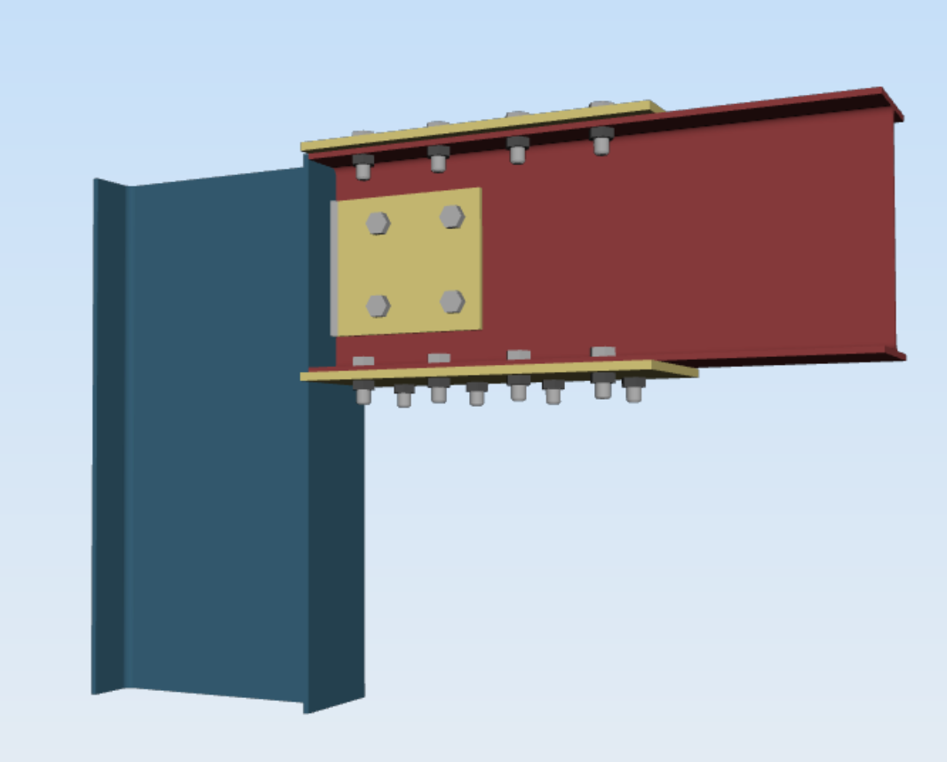
Flange Plate
A Flange Plate Moment Connection connects the flange of the column to the web of the beam member. A plate is either belted and/or welded to join the members to form a rigid fixture. An example of a flange plate moment connection can be seen from the adjacent image. This connection shows two yellow plates bolted to the flanges of the beam member to connect it to the column. As the beam undergoes bending, it will be passed onto the connection member.
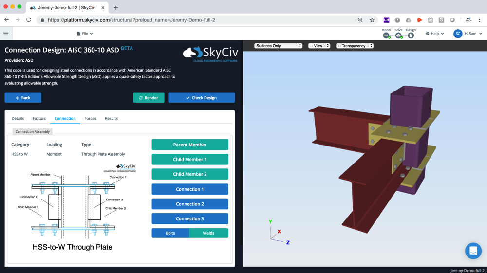
Through Plate
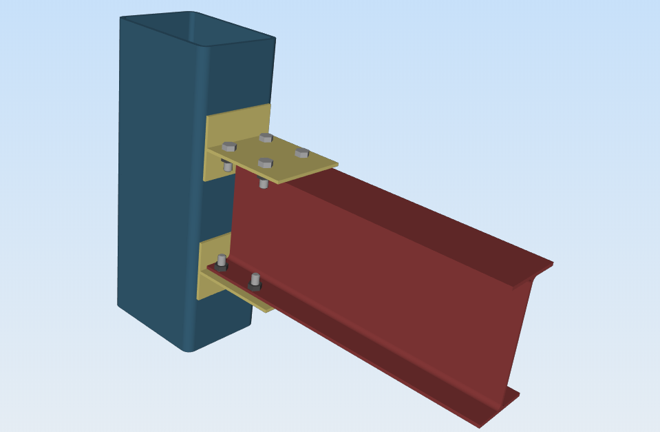
Through plates transfer moment between members through the use of a rigid plate that is either bolted or welded to the members. The rendering above is an example of a Through Plate connection. If the HSS column undergoes a bending force then intuitively it will transfer to the beam due to the yellow plate.
Collared Plate
Collared plates are fairly similar to through plates, however, the plate does not extend through the HSS section. Rather the plate sits comfortably around the HSS section and is then secured to the child (beam) members.
Directly Welded Connection
Directly welding a connection in every direction creates a very strong, rigid connection. By welding a plate between the beam and column (welding around all edges) means that movement and rotation is completely restricted and a moment connection is formed.
3D Representation of a Moment Connection (Through Plate Connection) – the horizontal yellow plate causes the moment force to be transferred from the Hollow Section to the I-Beam (and vice versa), making this a Moment Connection.
Moment Connection vs Shear Connection: the difference
The main difference is how the connection interacts between the member to member. A moment connection will cause a rotation effect between members. I.e. as member 1 bends, it will cause the connected member to bend as well. A shear connection has some freedom to rotate in the connection, so this does not happen. A shear connection will allow rotation and prevent the moment force to transfer. Below is a table summarizing the differences:
| Moment Connection | Shear Connection | |
|---|---|---|
| Forces Transferred | Shear and Moment | Shear only |
| Alternative names | Rigid, Fixed, Stiff | Pinned, Hinge |
| Rotation | Connection restricts rotation | Connection free to rotate |
| Software Fixity Code | FFFFFF | FFFFF |
SkyCiv Connection Design Software
The above info, screenshots, and 3D models of moment connections are from SkyCiv Steel Connection Design Software. The software will run design checks for the various design codes, including AISC 360-10 ASD and LRFD with full rendering, CAD export, and drawings. The software will also produce a step-by-step guide of the connection shear design calculations so that you can follow the steps it is taking.
You can try out the software with SkyCiv Free Steel Connection Calculator or sign up today to get started!