A Combined footing is a single footing supporting two or more columns. Combined footings are commonly used when columns are spaced too closely, where two isolated footings would be unsatisfactory. For example, with two isolated footings that are too close to each other, the soil beneath may share portions of influence zones, leading to a required extension of either or both of the isolated footings. Depending on physical or other constraints, this may not be possible.
SkyCiv Foundation Design module includes the design of combined footings conforming to the American Concrete Institute (ACI 318).
Want to try SkyCiv’s Foundation Design software? Our free tool allows users to perform load-carrying calculations without any download or installation!
Design of a Combined Foundation
Dimension Requirements
To determine the dimensions of a isolated footing, service or unfactored loads, such as dead (D), Live (L), Wind (W), Seismic (E), etc will be applied using Load Combinations, as defined by ACI 318-14. Whichever Load Combination governs will be considered the design load, and is compared to the allowable soil pressure as shown in Equation 1, as recommended in Section 13.2.6 of ACI 318-14.
\(\text{q}_{\text{a}} = \frac{ \text{P1}_{\text{n}} + \text{P2}_{\text{n}} }{\text{A}} \rightarrow \) Equation 1
where:
qa = net allowable soil pressure
P1n = unfactored loads at Column 1 (left)
P2n = unfactored loads at Column 2 (right)
A = Foundation area
From Equation 1, qa are interchange with A.
\(\text{A} = \frac{ \text{P1}_{\text{n}} + \text{P2}_{\text{n}} }{\text{q}_{\text{a}}} \rightarrow \) Equation 1a
At this point, the dimensions of the footing can be back-calculated from the required area dimension, A.
One-way Shear
The One-way shear limit state, also known as “flexural shear”, extends it critical section across the width of the footing and is located at a distance “d” from the face of a column, where Critical Plane Shear is located (Refer to Figure 1).
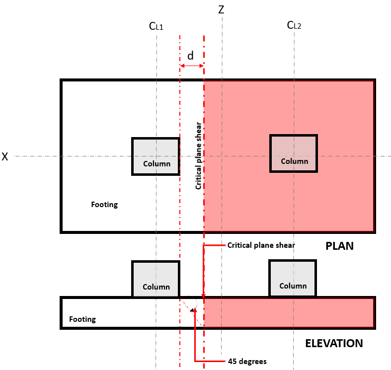
Figure 1. Critical plane shear of One-way shear
The One-way Shear Demand or Vu is calculated assuming the footing is cantilevered away from the column where the area is (red) indicated in Figure 1 in accordance of ACI 318-14, Section 8.5.3.1.1.
The One-way Shear Capacity or ϕVc is defined as Ultimate shear strength and calculated using Equation 2 per ACI 318-14, Section 22.5.5.1:
\(\phi\text{V}_{\text{c}} = \phi _{\text{shear}} \times 2 \sqrt{\text{f’}_{\text{c}}} \times \text{b}_{\text{w}} \times \text{d} \rightarrow \) Equation 2 (ACI Eq. 22.5.5.1 English)
or
\(\phi\text{V}_{\text{c}} = \phi _{\text{shear}} \times 0.17 \sqrt{\text{f’}_{\text{c}}} \times \text{b}_{\text{w}} \times \text{d} \rightarrow \) Equation 2 (ACI Eq. 22.5.5.1 Metric)
where:
ϕshear = shear design factor
f’c = specified concrete strength, psi or MPa
bw = thickness of the footing, in or mm
d = distance from extreme compression fiber to centroid of longitudinal tension reinforcement, in or mm
Shear Demand and Shear Capacity must meet the following equation to meet the design requirements of ACI 318-14:
\(\text{V}_{\text{u}} \leq \phi\text{V}_{\text{c}} \rightarrow \) Equation 3 (ACI Eq. 7.5.1.1(b))
SkyCiv Foundation, in compliance of Equation 3, calculates the one-way shear unity ratio (Equation 4) by taking Shear Demand over Shear Capacity.
\( \text{ratio} = \frac{\text{Shear Demand}}{\text{Shear Capacity}} \rightarrow \) Equation 4
Two-way Shear
The Two-way Shear limit state, also known as “punching shear”, extends it critical section to a distance “d/2” from the face of the column and around the perimeter of the column. The Critical Shear Plane is located at that section of the footing (Refer to Figure 2).
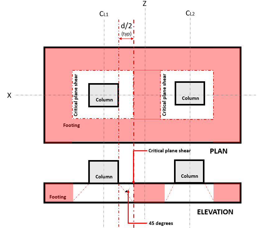
Figure 2. Critical plane shear of Two-way shear
The Two-way Shear Demand or Vu occurs at the Critical Shear Plane, located a distance of “d/2” where the (red) hatched area, indicated in Figure 2, in accordance of ACI 318-14, Section 22.6.4.
The Shear Capacity or ϕVc is governed by the smallest value calculated using Equation 5, 6, and 7 per ACI 318-14, Section 22.6.5.2:
\(\phi\text{V}_{\text{c}} = \phi _{\text{shear}} \times 4 \times \lambda \times \sqrt{\text{f’}_{\text{c}}} \rightarrow \) Equation 5 (ACI Eq. 22.6.5.2(a) English)
\(\phi\text{V}_{\text{c}} = \left ( 2 + \frac{4}{\beta } \right ) \times \lambda \times \sqrt{f’_{c}} \rightarrow \) Equation 6 (ACI Eq. 22.6.5.2(b) English)
\(\phi\text{V}_{\text{c}} = \left ( 2 + \frac{\alpha _{s} \times d }{b{o}} \right ) \times \lambda \times \sqrt{f’_{c}} \rightarrow \) Equation 7 (ACI Eq. 22.6.5.2(c) English)
or
\(\phi\text{V}_{\text{c}} = \phi _{\text{shear}} \times 0.33 \times \lambda \times \sqrt{\text{f’}_{\text{c}}} \rightarrow \) Equation 5 (ACI Eq. 22.6.5.2(a) Metric)
\(\phi\text{V}_{\text{c}} = 0.17 \times \left ( 1 + \frac{2}{\beta } \right ) \times \lambda \times \sqrt{f’_{c}} \rightarrow \) Equation 6 (ACI Eq. 22.6.5.2(b) Metric)
\(\phi\text{V}_{\text{c}} = 0.0083 \times \left ( 2 + \frac{\alpha _{s} \times d }{b{o}} \right ) \times \lambda \times \sqrt{f’_{c}} \rightarrow \) Equation 7 (ACI Eq. 22.6.5.2(c) Metric)
note: β is the ratio of long side to short side of the column, concentrated load, or reaction area and αs is given 22.6.5.3
where:
λ = modification factor to reflect the reduced mechanical properties of lightweight concrete relative to normalweight concrete of the same compressive strength
f’c = specified concrete strength, psi or MPa
d = distance from extreme compression fiber to centroid of longitudinal tension reinforcement, in.or mm
Shear Demand and Shear Capacity must meet the following equation to meet the design requirements of ACI 318-14:
\(\text{V}_{\text{u}} \leq \phi\text{V}_{\text{c}} \rightarrow \) Equation 8 (ACI Eq. 7.5.1.1(b))
SkyCiv Foundation, in compliance of Equation 8, calculates the two-way shear unity ratio (Equation 9) by taking Shear Demand over Shear Capacity.
\( \text{ratio} = \frac{\text{Shear Demand}}{\text{Shear Capacity}} \rightarrow \) Equation 9
Flexure
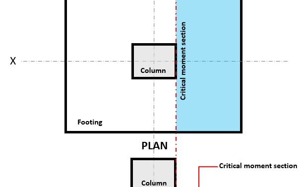
Figure 3. Critical moment section of Flexure
The Flexural limit state is occurs at the Critical Flexure Section, located at the face of the column on top of the footing (Refer to Figure 3).
The Flexural Demand, or Mu is located at the Critical Flexure Section (blue hatch area) indicated in Figure 3, and is calculated using Equation 10:
\( \text{M}_{u} = \text{q}_{u} \times \left ( \frac{l_{x}}{2} – \frac{c_{x}}{2} \right ) \times l_{z} \times \left ( \frac{\frac{l_{x}}{2} – \frac{c_{x}}{2} }{2} \right ) \rightarrow \) Equation 10
where:
qu = factored soil pressure, ksf or kpa
lx = footing dimension parallel to x-axis, in or mm
lz = footing dimension parallel to z-axis, in or mm
cx = column dimension parallel to x-axis, in or mm
The Flexural Capacity, or ϕMn is calculated using Equation 11:
\( \phi\text{M}_{n} = \phi_{\text{flexure}} \times A_{s} \times f_{y} \times \left( d – \frac{a}{2} \right) \rightarrow \) Equation 11
where:
ϕ = flexural design factor
lx = footing dimension parallel to x-axis, in or mm
lz = footing dimension parallel to z-axis, in or mm
d = distance from extreme compression fiber to centroid of longitudinal tension reinforcement, in or mm
As = reinforcement area, in2 or mm2
a = depth of equivalent rectangular stress block, in or mm
fy = steel strength, ksi or MPa
Moment Demand and Moment Capacity must meet the following equation to meet the design requirements of ACI 318-14:
\(\text{M}_{\text{u}} \leq \phi\text{M}_{\text{n}} \rightarrow \) Equation 12 (ACI Eq. 7.5.1.1(b))
SkyCiv Foundation, in compliance of Equation 12, calculates the flexural unity ratio (Equation 13) by taking Flexural Demand over Flexural Capacity
\( \text{ratio} = \frac{\text{Flexure Demand}}{\text{Flexure Capacity}} \rightarrow \) Equation 13

Albert Pamonag
Structural Engineer, Product Development
B.S. Civil Engineering
References
- Building Code Requirements for Structural Concrete (ACI 318-14) Commentary on Building Code Requirements for Structural Concrete (ACI 318R-14). American Concrete Institute, 2014.
- McCormac, Jack C., and Russell H. Brown. Design of Reinforced Concrete ACI 318-11 Code Edition. Wiley, 2014.
- Taylor, Andrew, et al. The Reinforced Concrete Design Handbook: a Companion to ACI-318-14. American Concrete Institute, 2015.