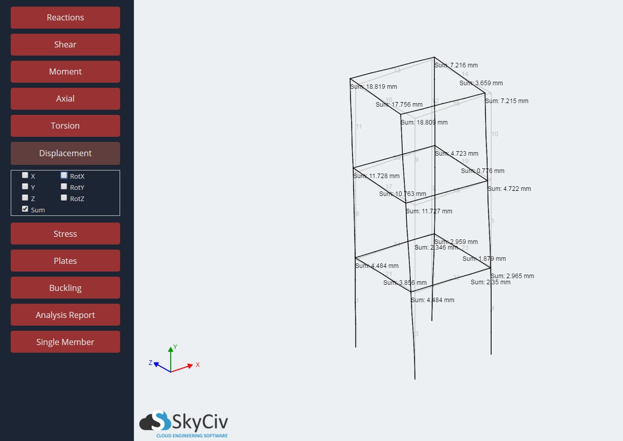
Display the single-member displacement values of each member of your structure. Values for displacement are shown at the starting and ending nodes of each member. Both distance and rotational displacement values can be turned on and off with the checkboxes. The values are separated into component global X, Y, and Z values (or sum for distance displacement).
Note, as is with the other display options, what is shown depends on the Load Combination/Envelope that is chosen in the dropdown on the left-hand side. The displacement labels can be dragged to improve clarity. You can reset the position of the labels by rotating or dragging the structure.
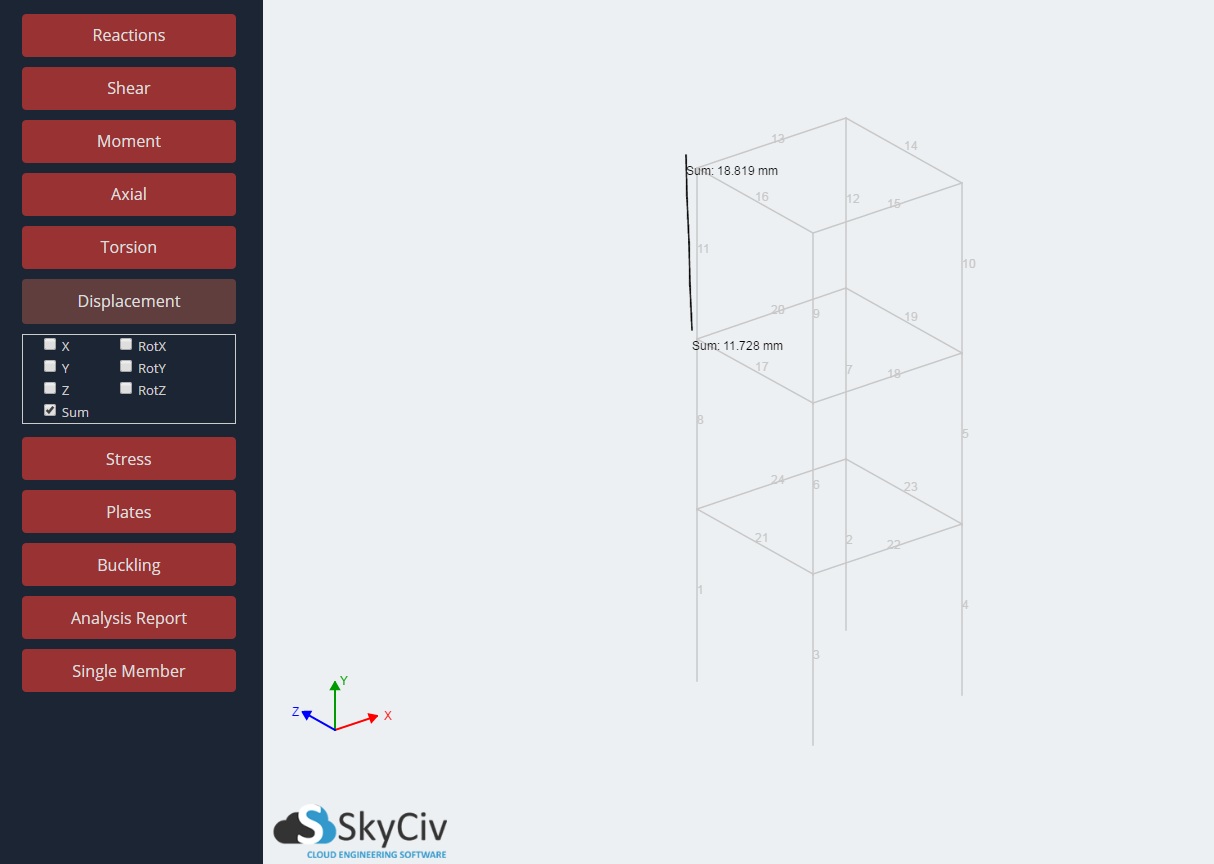
For example, with Displacement results turned on, the wireframe will always show the displaced shape of the model. You can toggle on and off any combination of displacement results as shown:
Scaling and Animating Deflection
It’s often helpful to scale or animate the deflection of your structure to review results or identify issues in your model. For instance, identifying disconnected members is much easier when animating the deflection of the structure:
To animate your deflection, simply scroll the vertical slider (on the right side of the screen) up and and down. Or simply, hold the “S” key and scroll the mouse (S is for Scale).
L/Deflection Ratio Results
This common ratio helps give users a quick ratio to use for deflection limits. It’s important to understand how the software calculates these values so the engineer can interpret the results correctly. This result is often expressed as L/xx. If the value, xx, is below a certain criterion (for example 250) it is considered to have failed that criteria. For more accurate analysis and checks, SkyCiv performs two deflection/span calculations:
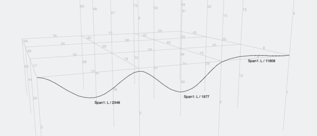
Span via Method 1: For continuous members, it assumes each node/connection along the member acts as a restraint or brace.
Span via Method 2: For continuous members, the span is taken over the entire length of the member regardless of the nodes/connections along the member.
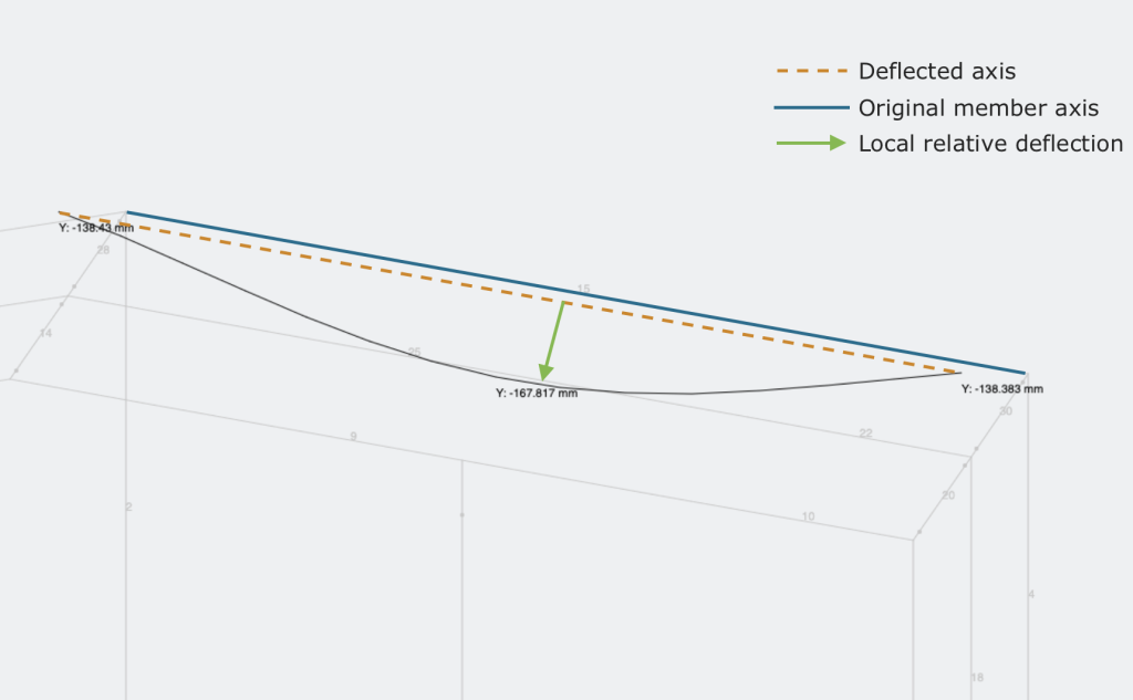
For both methods, SkyCiv calculates the denominator (the xx value) of this result by dividing the member’s length by the member’s local relative deflection. The local relative member deflection is the deflection from the line between the ends of the member’s deflected shape:
By utilizing both methods, SkyCiv can identify and correctly calculate governing deflection ratios in different scenarios. For example:
Example 1: Member 30 has restraint (via a connected member) at the midpoint, so span 1 is more suitable and should be considered:
Example 2: The bottom member has connected members, but not offering any restraint. So span 2 is more suitable and governs. The below diagram provides a simple explanation of the difference in the span ratios:
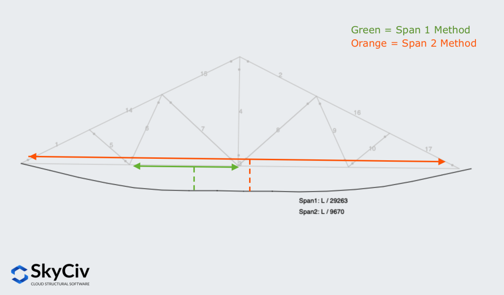
It’s important to consider both cases, since if we looked at traditional deflection span ratios (simply between two members), we might miss the global deflection of the entire truss, which is represented in the Span 2 Method.
Detailed Deflection Ratio Example
In Structural 3D, we calculate a deflection ratio for users by determining the deflection perpendicular to the displaced member axis, and compare this to the displaced length of the member. This is the local relative deflection as defined in the above section.
The green line on the graph indicates the deflection of the member from the displaced member axis. This is what S3D uses to determine the d / L value. We can backward calculate this deflection ratio using these values (also using the Single Member Analysis function in SkyCiv):
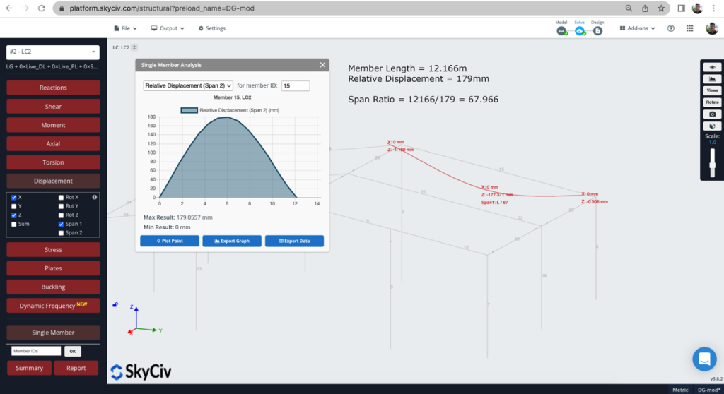
Length of member: 12.166m
Relative Displacement: 179mm
12166 / 179 = 67.96
The deflection ratio is therefor 1 / 67 (represented as L/67).
Note: the software will automatically round down to the nearest integer for conservatism.
Cantilever deflections
Computing the relative displacement of a cantilever is often difficult and, in practice, not very informative. Engineers typically care about the absolute tip displacement, since this governs serviceability and user perception of deflection. For this reason, when SkyCiv identifies a member as a cantilever, it assigns the value of absolute displacement to the relative displacement field.
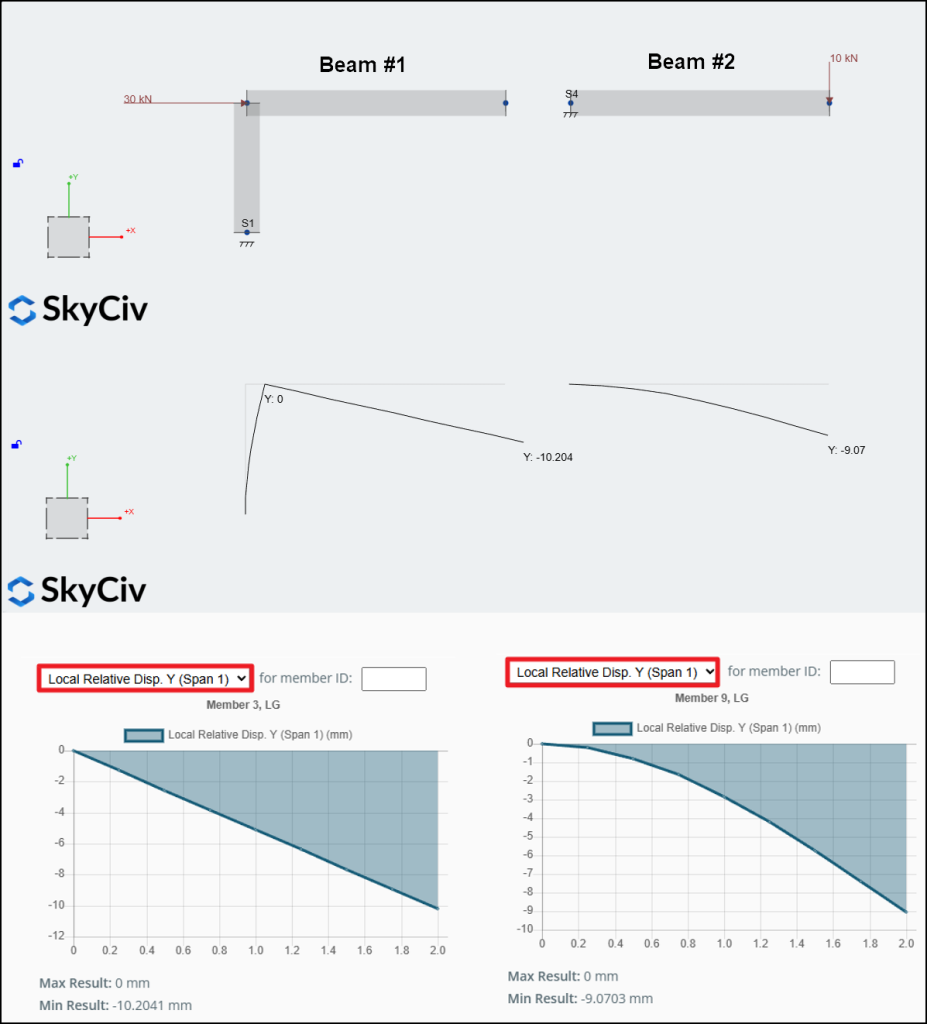
The figure below illustrates the concept:
- Beam #1: The tip displacement is caused mainly by rigid-body motion, not by internal strain. Theoretically, this should give a relative displacement of 0 mm and an absolute displacement of 10.2 mm. However, because the member is detected as a cantilever, SkyCiv reports a relative displacement of 10.2 mm at the tip.
- Beam #2: SkyCiv matches the theoretical behavior. The internal bending of the member produces a tip displacement of 9.07 mm, which is the same for both the relative and absolute values.
Adjusting the relative displacement of cantilevers to match the absolute displacement allows the serviceability check, which checks the span over deflection ratio against the relative displacement, to remain accurate in both cases.
Automatic cantilever detection
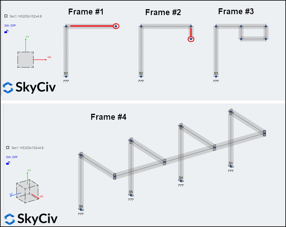
The cantilever detection algorithm in SkyCiv is quite simple: If a member has a free end with no other members attached, it will be considered a cantilever. Users should review deflection limits when dealing with more complex arrangements where additional members connect to the free end of a cantilevered member. In the example below, the free tips and cantilever members are shown in red:
- Frame 1: Only the horizontal beam is automatically detected as a cantilever, even though some may argue that the column behaves like one as well.
- Frame 2: Neither the beam nor the column is detected, but the suspended member is considered a cantilever.
- Frame 3: No cantilever members are detected.
- Frame 4: No cantilever members are detected.
As previously stated, in all four cases, users must exercise caution in interpreting the results.