A walkthrough of the calculations to design an isolated footing (ACI 318-14)
The foundation is an essential building system that transfers column and wall forces to the supporting soil. The engineer might opt for a shallow or deep foundation system based on the soil characteristics and building loads.
SkyCiv FoundationDesign Module includes analyzing and designing isolated footing conforming to the American code ACI318-14.
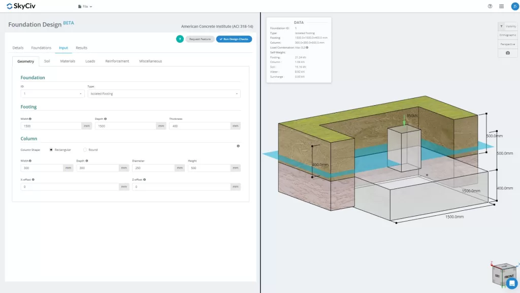
Want to try SkyCiv’s Foundation Design software? Our tool allows users to perform Foundation Design calculations without downloading or installing!
A Step-by-Step Guide to Designing an Isolated Footing
Dimension Requirements
To determine the dimensions of an isolated footing, service or unfactored loads, such as dead (D), Live (L), Wind (W), Seismic (E), etc will be applied using Load Combinations, as defined by ACI 318-14. Whichever Load Combination governs will be considered the design load, and is compared to the allowable soil pressure as shown in Equation 1, as recommended in Section 13.2.6 of ACI 318-14.
\(\text{q}_{\text{a}} = \frac{\text{P}_{\text{n}}}{\text{A}} \rightarrow \) Equation 1
qa = Allowable soil pressure
Pn = Unfactored design load
A = Foundation area
The footing dimensions can be initially estimated by solving the foundation area (A) using Equation 1.
\(\text{A} = \frac{\text{P}_{\text{n}}}{\text{q}_{\text{a}}} \rightarrow \) Equation 1a
One-way Shear
The one-way shear limit state, also known as beam shear, recognizes that the footing may fail in shear similar to a wide beam along a critical shear plane located at a distance “d” from the face of the column (Figure 1),
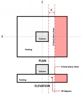
Figure 1. Critical Plane Shear of One-way shear
The One-way Shear Demand or Vu is calculated assuming the footing is cantilevered away from the column where the red area is indicated in Figure 1, following Section 8.5.3.1.1.
The One-way Shear Capacity or ϕVc is defined as the Ultimate shear strength and calculated using Equation 2 per Section 22.5.5.1.
\(\phi\text{V}_{\text{c}} = \phi _{\text{shear}} \times 2 \sqrt{\text{f’}_{\text{c}}} \times \text{b}_{\text{w}} \times \text{d} \rightarrow \) Equation 2 ( Section 22.5.5.1, Imperial)
or
\(\phi\text{V}_{\text{c}} = \phi _{\text{shear}} \times 0.17 \sqrt{\text{f’}_{\text{c}}} \times \text{b}_{\text{w}} \times \text{d} \rightarrow \) Equation 2 (Section 22.5.5.1, Metric)
ϕshear = Shear design factor
f’c = Specified concrete strength, (psi, MPa)
bw = Width of the footing, (in, mm)
d = Distance from extreme compression fiber to centroid of longitudinal tension reinforcement, (in, mm)
Shear Demand and Shear Capacity must meet the following equation to meet the design requirements of ACI 318-14:
\(\text{V}_{\text{u}} \leq \phi\text{V}_{\text{c}} \rightarrow \) Equation 3 (ACI Eq. 7.5.1.1(b))
SkyCiv Foundation Design Module, in compliance with Equation 3, calculates the one-way shear utility ratio (Equation 4) by taking Shear Demand over Shear Capacity.
\( \text{Utility Ratio} = \frac{\text{Shear Demand}}{\text{Shear Capacity}} \rightarrow \) Equation 4
Two-way Shear
The Two-way Shear limit state, also known as punching shear, extends its critical section to a distance “d/2” from the face of the column and around the perimeter of the column (Figure 2).
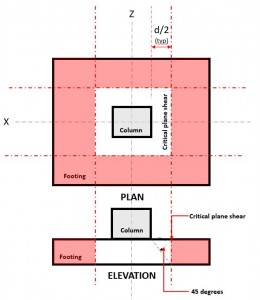
Figure 2. Critical Shear Plane of Two-way shear
The Two-way Shear Demand or Vu occurs at the Critical Shear Plane, located at a distance of “d/2” where the (red) hatched area, indicated in Figure 2, following Section 22.6.4.
The Shear Capacity or ϕVc is governed by the smallest value calculated using Equations 5, 6, and 7 per Section 22.6.5.2
\(\phi\text{V}_{\text{c}} = \phi _{\text{shear}} \times 4 \times \lambda \times \sqrt{\text{f’}_{\text{c}}} \rightarrow \) Equation 5 (Section 22.6.5.2(a) Imperial)
\(\phi\text{V}_{\text{c}} = \left ( 2 + \frac{4}{\beta } \right ) \times \lambda \times \sqrt{f’_{c}} \rightarrow \) Equation 6 (Section 22.6.5.2(b) Imperial)
\(\phi\text{V}_{\text{c}} = \left ( 2 + \frac{\alpha _{s} \times d }{b{o}} \right ) \times \lambda \times \sqrt{f’_{c}} \rightarrow \) Equation 7 (Section 22.6.5.2(c) Imperial)
or
\(\phi\text{V}_{\text{c}} = \phi _{\text{shear}} \times 0.33 \times \lambda \times \sqrt{\text{f’}_{\text{c}}} \rightarrow \) Equation 5 (Section 22.6.5.2(a) Metric)
\(\phi\text{V}_{\text{c}} = 0.17 \times \left ( 1 + \frac{2}{\beta } \right ) \times \lambda \times \sqrt{f’_{c}} \rightarrow \) Equation 6 (Section 22.6.5.2(b) Metric)
\(\phi\text{V}_{\text{c}} = 0.0083 \times \left ( 2 + \frac{\alpha _{s} \times d }{b{o}} \right ) \times \lambda \times \sqrt{f’_{c}} \rightarrow \) Equation 7 (Section 22.6.5.2(c) Metric)
Note: β is the ratio of the long side to the short side of the column, concentrated load, or reaction area and αs is given by 22.6.5.3
λ = Modification factor to reflect the reduced mechanical properties of lightweight concrete relative to normal concrete of the same compressive strength
f’c = Specified compressive concrete strength (psi, MPa)
d = Distance from extreme compression fiber to centroid of longitudinal tension reinforcement, (in, mm)
Shear Demand and Shear Capacity must meet the following equation to meet the design requirements of ACI 318-14:
\(\text{V}_{\text{u}} \leq \phi\text{V}_{\text{c}} \rightarrow \) Equation 8 (Section 7.5.1.1(b))
SkyCiv Foundation Design Module, in compliance with Equation 8, calculates the two-way shear Utility ratio (Equation 9) by taking Shear Demand over Shear Capacity.
\( \text{Utility Ratio} = \frac{\text{Shear Demand}}{\text{Shear Capacity}} \rightarrow \) Equation 9
Flexure
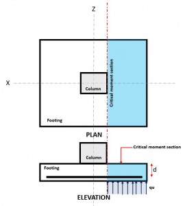
Figure 3. Critical Flexure Section
The Flexural limit state occurs at the Critical Flexure Section, located at the face of the column on top of the footing (Figure 3).
The Flexural Demand or Mu is located at the Critical Flexure Section (blue hatch area) indicated in Figure 3, and is calculated using Equation 10.
\( \text{M}_{u} = \text{q}_{u} \times \left ( \frac{l_{x}}{2} – \frac{c_{x}}{2} \right ) \times l_{z} \times \left ( \frac{\frac{l_{x}}{2} – \frac{c_{x}}{2} }{2} \right ) \rightarrow \) Equation 10
qu = factored soil pressure, (ksf, kPa)
lx = footing dimension along the x-axis (in, mm)
lz = footing dimension along the z-axis (in, mm)
cx = column dimension along the x-axis (in, mm)
The Flexural Capacity or ϕMn is calculated using Equation 11.
\( \phi\text{M}_{n} = \phi_{\text{flexure}} \times A_{s} \times f_{y} \times \left( d – \frac{a}{2} \right) \rightarrow \) Equation 11
ϕ = flexural design factor
lx = footing dimension parallel to x-axis (in , mm)
lz = footing dimension parallel to z-axis (in , mm)
d = distance from extreme compression fiber to centroid of longitudinal tension reinforcement (in , mm)
As = reinforcement area (in2 , mm2)
a = depth of equivalent rectangular stress block (in , mm)
fy = reinforcement strength, (ksi, MPa)
Moment Demand and Moment Capacity must meet the following equation to meet the design requirements of ACI 318-14:
\(\text{M}_{\text{u}} \leq \phi\text{M}_{\text{n}} \rightarrow \) Equation 12 (Section 7.5.1.1(b))
SkyCiv Foundation Design Module, in compliance with Equation 12, calculates the flexural utility ratio (Equation 13) by taking Flexural Demand over Flexural Capacity.
\( \text{Utility Ratio} = \frac{\text{Flexure Demand}}{\text{Flexure Capacity}} \rightarrow \) Equation 13
Additional Verifications
Other verifications not mentioned by the code, including soil pressure checks, uplift, and other stability checks are also verified.
Soil Pressure
The determination of base pressure or the interaction between the soil and footing primarily relies on the footing dimensions and the resulting eccentricity of the applied loads. Depending on the positioning of this resulting eccentricity, the base pressure can induce full or partial compression on the footing. This assessment enables us to confirm whether the underlying soil can sustain the entirety of the loads transmitted from the footing.
For a detailed guide for manually calculating the soil pressure, please refer to this link: Pressure Distribution Under a Rectangular Concrete Footing
The utility ratio is evaluated by comparing the maximum soil pressure (serviceability state) with the allowable gross bearing soil capacity:
\( \text{Utility Ratio} = \frac{\text{Max. Soil Pressure}}{\text{Gross Allowable Soil Bearing Capacity}} \rightarrow \) Equation 14
Uplift
Checks the governing axial load acting on the footing. Sums all vertical loads including the user load and self-weights of the column, footing slab, soil, and buoyant force. If the column experiences an upward force, the self-weights specified must counterbalance the upward force; otherwise, the design risks failure due to instability.
Overturning
Overturning of the footing is checked by summing up all moments about a point in the footing including all the forces acting on it. All serviceability load combinations must be considered to check the governing overturning moment. Usually, a safety factor of 1.5-2 is employed to evaluate whether the footing passes the overturning check.
Sliding
To check for sliding, the sum of the horizontal resisting loads pointing to the right is divided by the sum of the loads pointing to the left.
- Resisting loads:
- Horizontal force due to friction between the footing base and the substructure soil
- Passive soil pressure (if included)
- Sliding loads:
- The horizontal component of the active soil pressure
- The horizontal component of the surcharge resultant pressure
Generally, a minimum factor of safety of 1.5 is used. If no horizontal force is acting on the footing, checking for sliding is not required.
SkyCiv Foundation Design Module
The Foundation Design Module is a powerful tool integrated with Finite Element Analysis (FEA), capable of conducting thorough soil pressure and wood armer analyses for detailed flexural checks. It performs all structural checks specified by ACI 318 and other verifications mentioned above and presents them in a comprehensive report.
Get Started with SkyCiv Foundation today!
Launch the Foundation Design and try it today! It’s easy to get started but if you need more help, then be sure to visit our documentation or get in touch with us!
Not a SkyCiv User? Sign up for a Free 14 Day Trial to get started!

Product Developer
BSc (Civil), MSc (Civil)

Albert Pamonag
Structural Engineer, Product Development
M.E. Civil Engineering
References
- Building Code Requirements for Structural Concrete (ACI 318-14) Commentary on Building Code Requirements for Structural Concrete (ACI 318R-14). American Concrete Institute, 2014.
- McCormac, Jack C., and Russell H. Brown. Design of Reinforced Concrete ACI 318-11 Code Edition. Wiley, 2014.
- Taylor, Andrew, et al. The Reinforced Concrete Design Handbook: a Companion to ACI-318-14. American Concrete Institute, 2015.