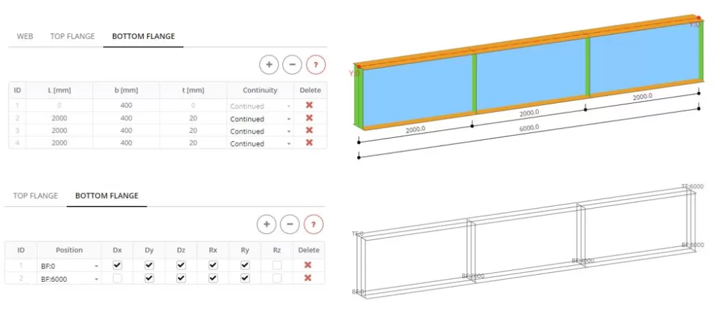
Flange
Boundaries can be defined for the nodes arranged on the flange part edges defined in the Main Parts > Flanges. Here in the panel tab, you select the top or bottom flange of a beam and in each table row, you define the position of the flange edge and make displacement restrictions for nodes. If you click on the Preview button you may see the nodes of the selected edges for which the boundaries will be applied
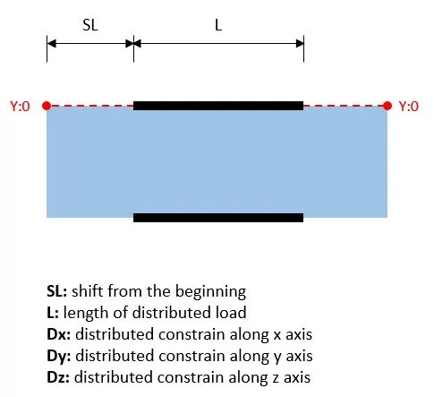
Examples of input
The distributed boundaries are applied to the nodes of the top and bottom edges of a beam web. Here you select the flange on which the boundaries are applied, from where the distribution is started (SL), the length of distribution (L), and the direction of constrains. If you click on the Preview button you may see the nodes of the selected edges for which the boundaries will be applied.
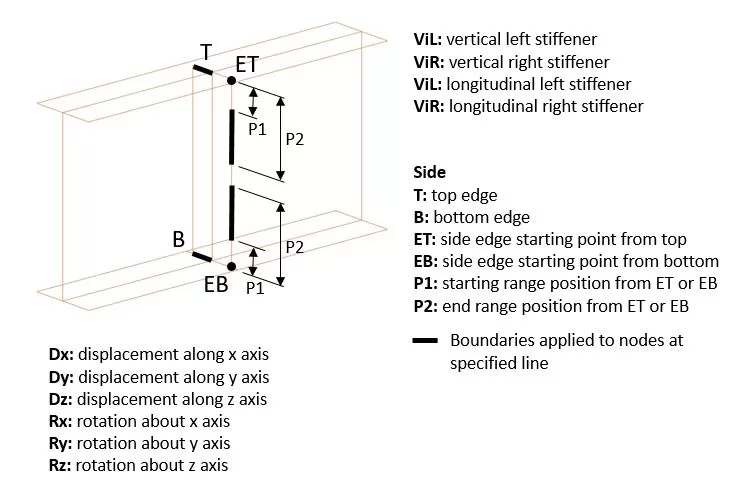
Stiffeners
Boundaries can be defined for the nodes arranged on the edges of stiffeners. Here in the table row you select the stiffener and its edge and then make displacement restrictions for nodes. If you click on the Preview button you may see the nodes of the selected edges for which the boundaries will be applied.
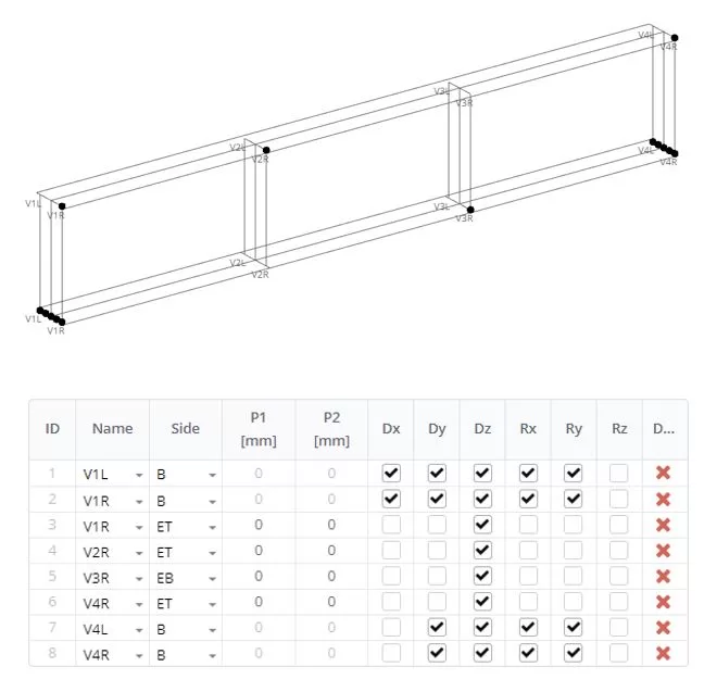
Example of input
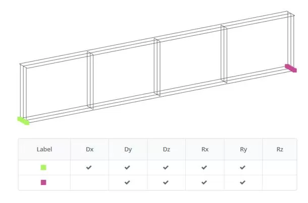
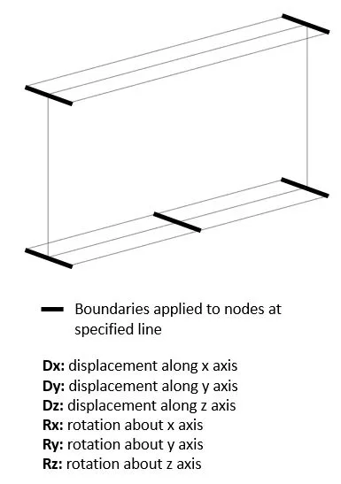
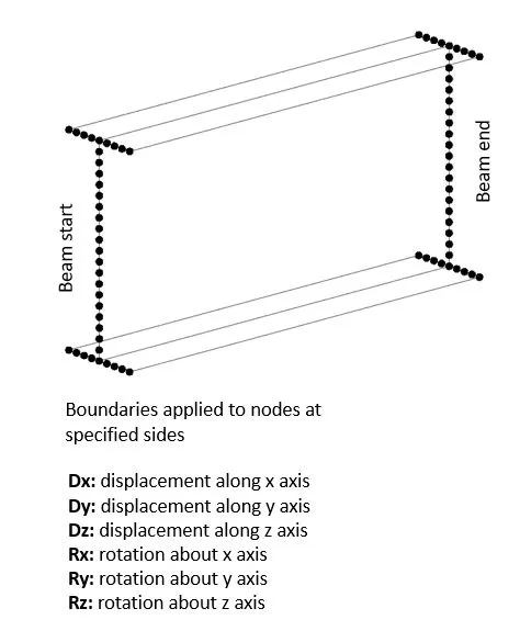
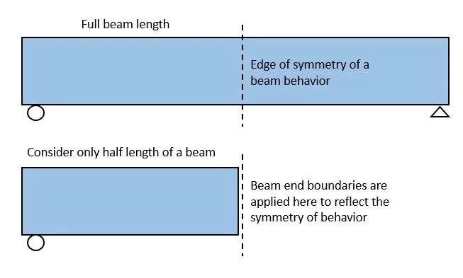
Ends
The boundaries can be applied to all the nodes that lie on the starting and ending edges of a beam. This can be suitable if you have a beam symmetrical and distributed forces in the parts symmetrically. Then you create a model that reflects the half of the beam and apply boundaries of symmetry on the corresponding edge. If you click on the Preview button you may see the nodes of the selected edges for which the boundaries will be applied.
Rigid Ends
In case when you need to consider beam left or right side section displacement or rotation (to reflect the pinned joint behavior) you can select the beam end and define the boundaries. The side section will be considered as the rigid body system with the master node at the section centroid and all the side edge nodes will be slave nodes. If you click on the Preview button you may see the nodes of the selected edges for which the boundaries will be applied.
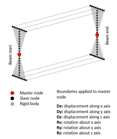
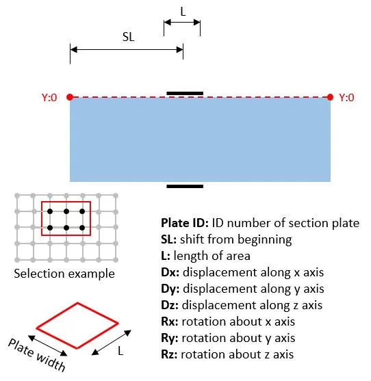
Plate Area
The boundaries are applied to the plate portion. Here you select the plate ID, position of the center of an area from the left side (SL), length (L), and width (B) of the area, and node constrains. The boundaries will be distributed among the nodes inside the area. The nodal constrains can be previewed by clicking on the Preview button.
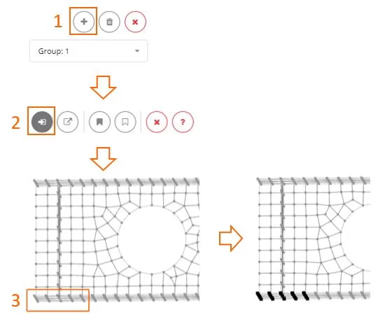
Custom Nodes
Start by creating a new group using the ‘+’ button. Then, select the nodes using pick, frame or polygon selection method and define constraints for them. If you need different constraints, create another group. Selection or deselection can be achieved using either the frame or polygon tools.
Preview All
The boundaries can be defined by different methods and for visual inspection of the finial node constrains you can check it in the table and 3D view.