The purpose of this article is to illustrate how the SkyCiv Foundation can be used with a real project. This includes: computing the service level capacity for bearing pressure, footing stability, size of footing; and strength level for the foundation thickness and reinforcement. Although the real project mentioned in this article does contain steel members, we will only be focusing on foundation design.
Project Background
This featured project was designed and built by BetaQuad Construction and Service Co., and is located in Central Luzon, Philippines. It is used for commercial cement production, having a daily production capacity of 30,000 metric tons. The overall footprint of the project during construction was approximately 800 m2. Seen below, the steel portion of the structure is acting as a lateral load resisting frame (3F with mezzanine). In all this project has 43 isolated footings that are needed for structural design.
The Design code basis that applied for the Foundation design was NSCP 2015. NSCP 2015 is similar to ACI 318-14 code , which ACI 318-14 is available on our SkyCiv Foundation Design Module.
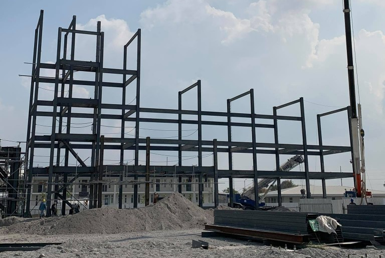
Figure 1 : On-site photo of the project during construction
SkyCiv Model and Parameters
Modeling the above structure in the SkyCiv Structural 3D platform means that the designers were able to take advantage of the various modeling tools that are available for all SkyCiv users.
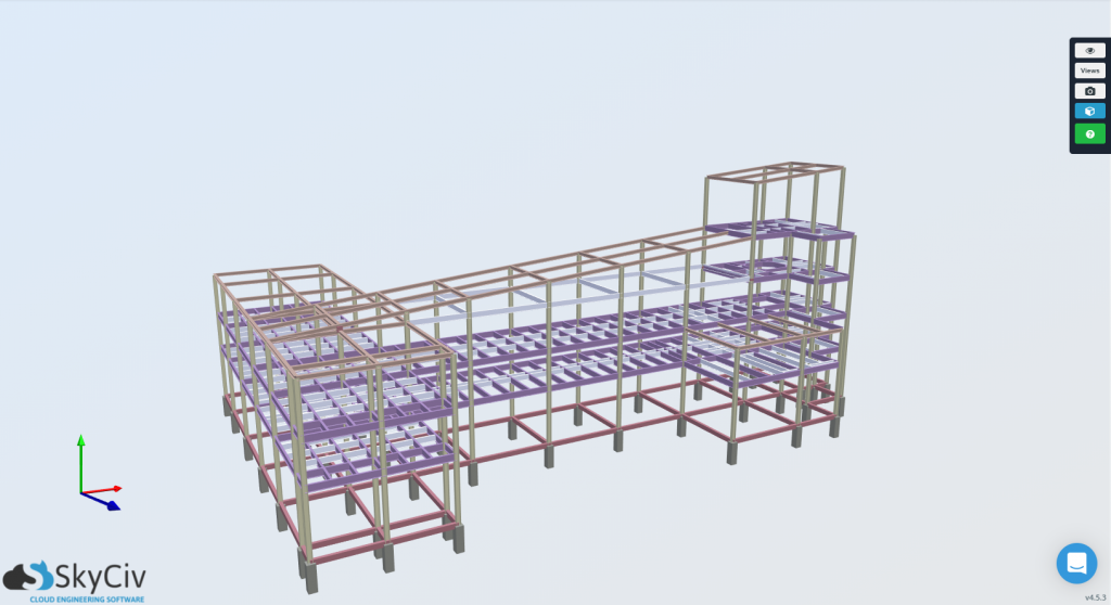
Figure 2 : 3D Rendering of the SkyCiv Structural 3D Model
Building Parameters
For a footing design, the most important building parameters that are needing for isolated footing design would be the seismic characteristics of the site, and the material properties of the footing. For this project’s location in Central Luzon, Philippines, the corresponding seismic zone is Seismic Zone 4.
For the foundation materials, 20.68 MPa strength concrete was used along with 415 MPa yield strength reinforcement steel. It is important when going through a Foundation design using the SkyCiv Foundation Design module, or any software, that these material properties are entered correctly, or else there will be rippling ramifications for the design.
Geotechnical Recommendations
Most projects require geotechnical reports, that outline the properties of the soil and overall characteristics from the site. Using the geotechnical information provided by the geotechnical engineer of this project, the site was found to have the following properties:
Soil Height = 2 meters
Soil Bearing Capacity = 192 KPa.
Soil Unit Weight = 16 kN/m3
These characteristics are required when designing any type of foundation, and therefore should be recorded for later input the SkyCiv Foundation module.
Load Combinations
The SkyCiv Foundation Design Module can perform the basic load combinations and are represented as Service and Factored Loads. Also, the design module will automatically consider seismic parameters when Earthquake Loads (E) have any value in the input.
For Geotechnical Design (Service Level):
The applicable load combinations for geotechnical design, which are applicable for both ASCE 7-10 and NSCP 2015 design codes, are the following:
[1] D + L
[2] D + L + E/1.4
[3] D + E/1.4
For Structural Design (Factored Level):
The application load combinations for structural design which are applicable for both ASCE 7-10 and NSCP 2015 design codes are the following:
[1] 1.4D
[2] 1.2D + 1.6L
[3] 1.2D + 1.0E + 1.0L
[4] 0.9D + 1.0E
Design of the Foundations
The actual workflow of the design of the foundations comes right after the completion of the structural analysis of our structure, where we can interpret the structures reactions.
Structural Analysis Results & Reactions
Before going into the Foundation module to design the footings of the project, the base column reactions for each footing should be noted in analysis portion of Structural 3D so they can be inputted in the foundation design module. These reactions were determined from a structural analysis. Using Envelope results, the worst case for each foundation were taken. These forces were exported via a .CSV file in an easily tabulated form to be copied into the Foundation Design Module.
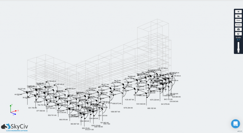
Figure 3-a: Column Base Reactions from the Structural 3D Model
In Figure 3-a, the S3D presents the reaction loads which can be extracted and imported to SkyCiv Foundation Design Module.
Input & Output of the Foundation module
With the forces recorded, the SkyCiv Foundation module can be used to analyse and check the designs of these footings. The module allows engineers to add as many foundations as required for the project. So in this case, the engineers designed and checked the 43 footings independently. Figure 3-b shows the user interface and presentation when there is more than one foundation being considered for design.
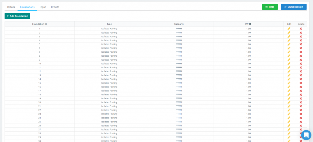
Figure 3-b: Foundation Design Tab
Going further, each foundation design incorporates an easy-to-use, linear workflow, where all of the recorded information from previous steps can be inputted.
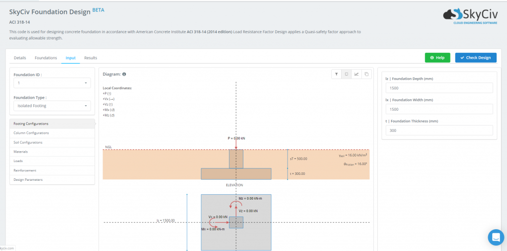
Figure 3-c: Foundation Design Module User Interface
Once the design requirements are established and the material properties and loads are inputted, the footing is ready for design. The presentation of the design results after clicking the Check Design button can be seen in Figure 3-d. These results are easily understandable, as they are presented as unity ratios. These ratios present the Experienced/Capacity for each individual limit state. When one is found to be over 1.0, the Status of the footing will turn Red and show “Fail”. Otherwise, that cell will be green and show “Pass”. This makes it easy to quickly check which foundations may need tweaking or more work in the design process.

Figure 3-d: Sample Design Results
As indicated in Figure 3-d, the five different limit states that are checked during the design are:
- Footing Size
- Stability such as Overturning and Sliding
- One-Way Shear
- Two-Way Shear
- Flexure
To dig deeper into the unity ratios of each limit state, engineers can view the Foundation Design Reports, which are accessible for each foundation. These reports open up the blackbox of structural engineering software by providing diagrams and detailed hand calculations together in a professional PDF that can be exported and used for project use. See Figure 3-e below to see how one of these reports looks:
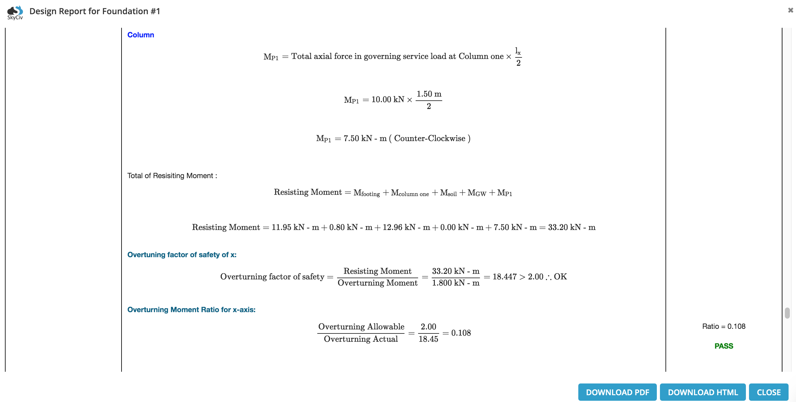
Figure 3-e: Example excerpt from a detailed Foundation Design report

Albert Pamonag, M.Eng
Structural Engineer, Product Development