Example Overview
In this example you will learn the basic steps of beam model creation, meshing, materials, boundary conditions and loads input. An analysis will be performed using linear static and linear buckling analysis.
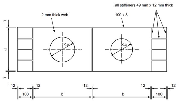
The example shown in this tutorial is the beam with a total length 1700 mm and a depth of 500 mm. The web has thickness 2 mm and there are two web openings (circular shape) with diameters 400 mm and 350 mm. The top and bottom flanges have a width 100 mm and thickness 8 mm. The beam web is stiffened from both sides by vertical stiffeners and longitudinal stiffeners (at the ends). The vertical stiffeners make two main web panels of length 750 mm. All stiffeners have width 50 mm and thickness 12 mm. The beam is loaded by a concentrated vertical force located at the top of the vertical stiffeners in the middle, and the beam has two supports below the second and the fourth vertical stiffeners.
The beam is made of steel with yielding stress 230 MPa for the web, and 245 MPa for other elements.
The current example represents the experimental test from the paper “Ultimate Behavior of Perforated Steel Plate Girders Subjected to Shear Loading. Alireza Bahrami, Mahdi Najarnasab. The Open Construction and Building Technology Journal”.
Step 1. Web
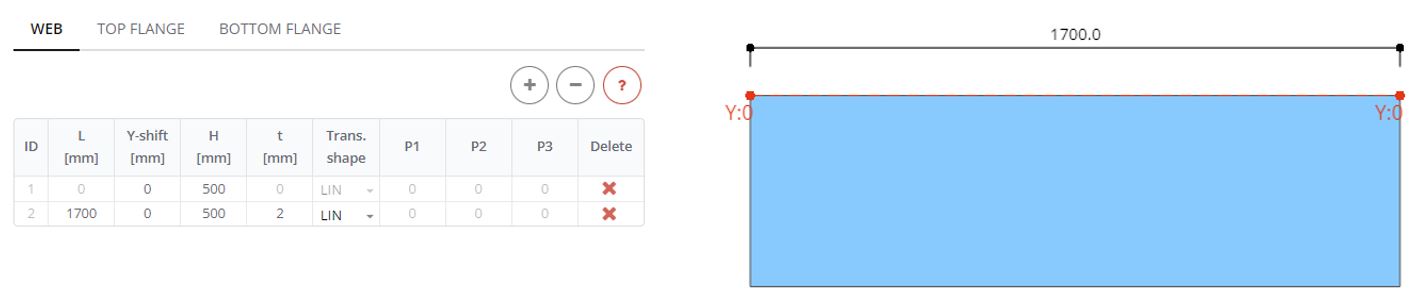
In the Web panel define the web with length (L) 1700 mm, depth (H) 500 mm and thickness (t) 2 mm.
Step 2. Flanges
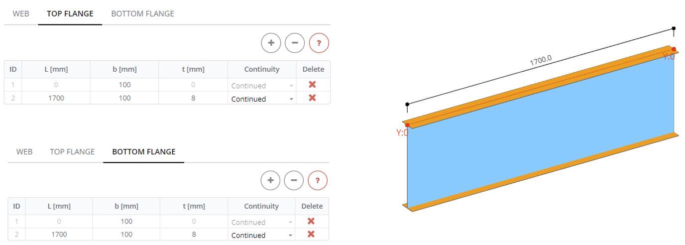
In the Flange panel define top and bottom flanges the full length of the web (L) 1700 mm, with starting and ending width (b) 100 mm and thickness (t) 8 mm
Step 3. Vertical Stiffeners
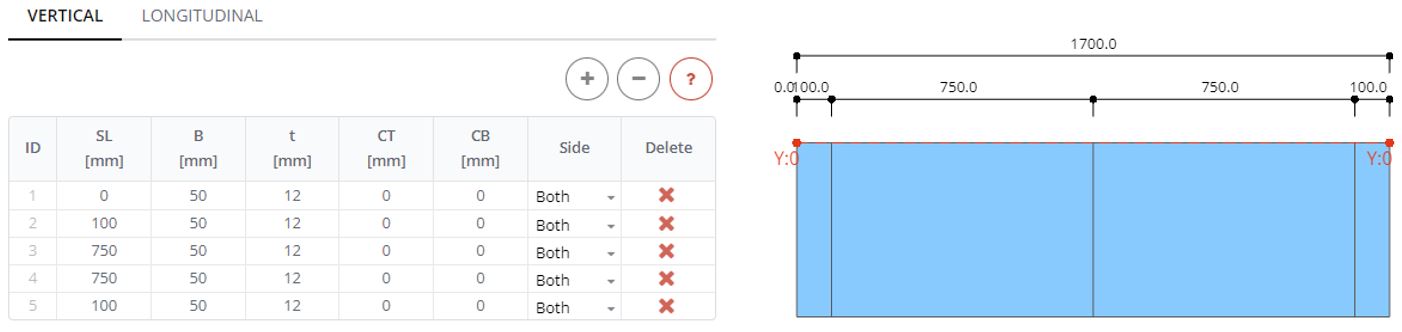
In the Vertical Stiffener panel define stiffeners with spans (SL) 100, 750, 750 and 100 mm from the left side of the beam. Define them all with the width (B) 50 mm and thickness (t) 12 mm.
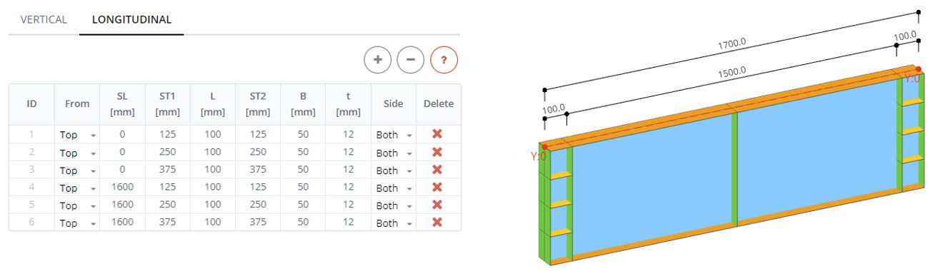
Step 4. Longitudinal Stiffeners
In the Longitudinal Stiffener panel define 6 stiffeners. At the beginning of the beam (SL: 0 mm) define 3 stiffeners with length (L) 100 mm and position from top (ST1, ST2) 125, 250, and 375 mm. The other three stiffeners start from the distance (SL) 1600 mm. Width (B) and thickness (t) are the same as for vertical stiffeners.
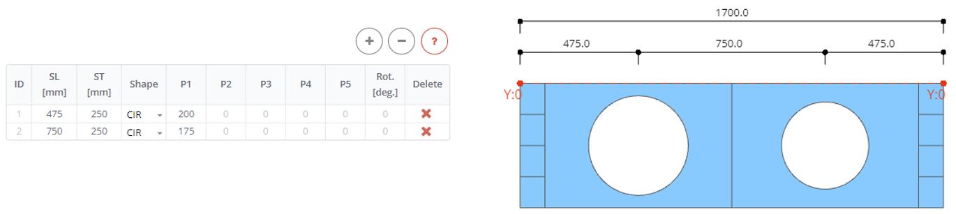
Step 5. Web Openings
In the Web Openings panel define two openings. They both have CIR shapes (circular shape) with a radius (P1) 200 and 175 mm. One opening is arranged at (SL) 475 mm from the left, and the second at 750 mm. The opening center is shifted from the top (ST) on 250 mm.
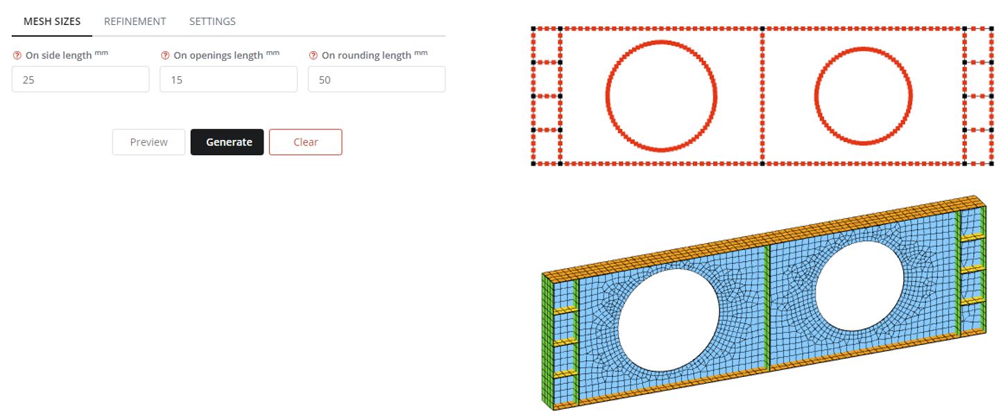
Step 6. Meshing
In the Mesh panel define mesh element sizes on the side length as 25 mm, and on the opening length as 15 mm. The 25 mm side length will be applied for web, flanges, and stiffeners edges. The 15 mm opening length will be applied for the opening edges. Click the Preview button to see the potential FE nodes distribution. Click the Generate button to create the FE mesh for analysis.
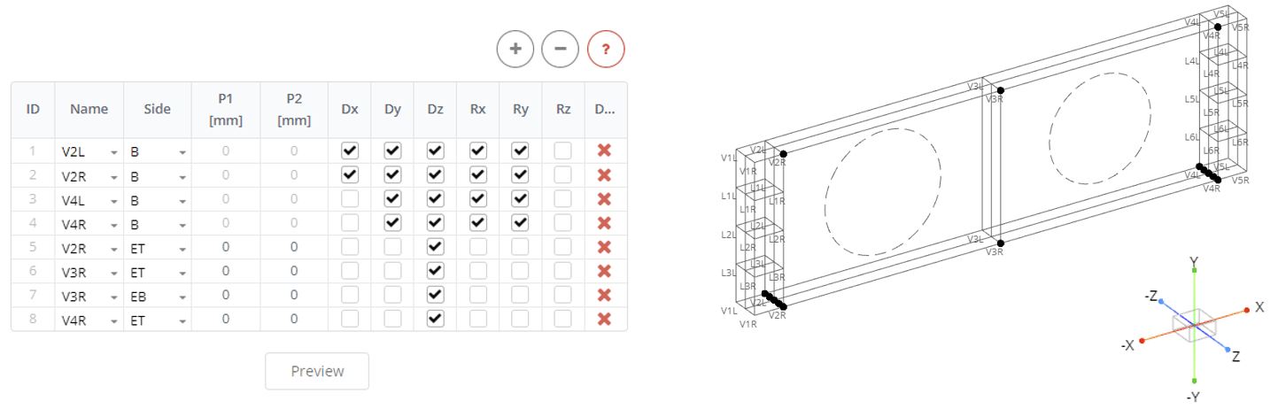
Step 7. Boundaries
In the Boundary Stiffeners panel define constrains for the beam. Here one pin and one roller supports are at the bottom of stiffener 2 and stiffener 4. Define the first two rows in the table as the left and right parts of the stiffener 2 (Name: V2L, V2R). Define the side of the stiffeners to be constrained (B). Follow the global axis to define restrictions for the nodes (pinned support has only one release for rotation about z-axis). The other two rows in the table corresponded to the roller support, below the parts of the vertical stiffener 4 (Name: V4L, V4R). The beam has no lateral translations. Define next 4 rows in the table for right side of the stiffener V2R, V3R, V4R, select ET and EB, and define restrictions only along axis Z. Click on the Preview button to see the nodes with constrains.
Step 8. Loads
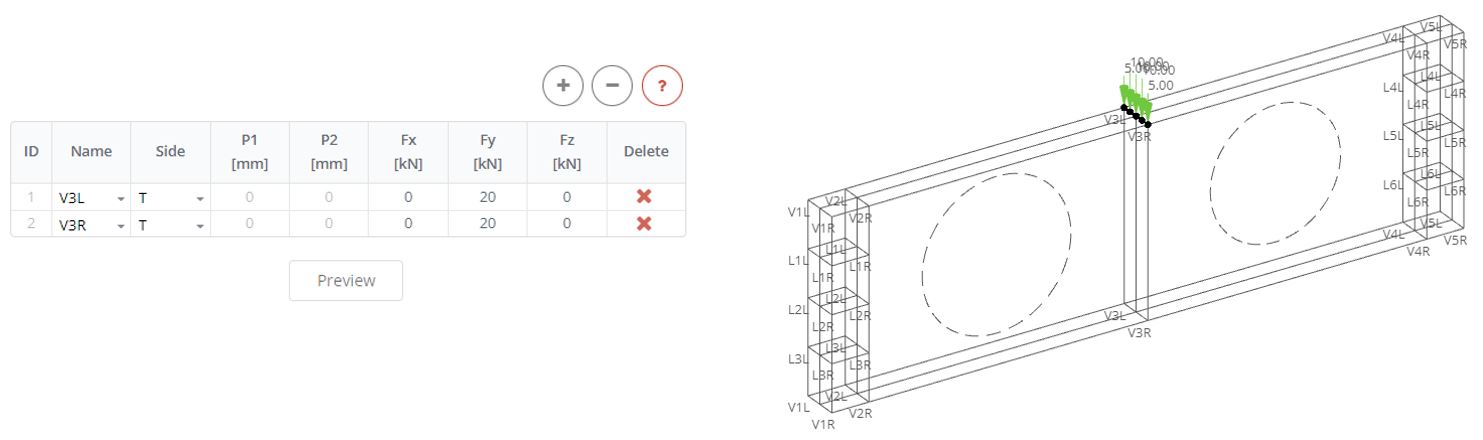
In the Stiffener Loads panel define the concentrated load at the middle of the beam. The load has value 40 kN and will be applied on top of two vertical stiffeners. In the table define two rows, select left and right parts of the stiffener 3 (V3L, V3R). Apply half of the load (Fz: 20 kN) to the top side (T) of each part of the stiffener. Click Preview to see how the load is distributed in FE nodes.
Step 9. Analysis
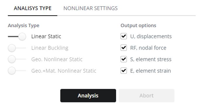
Select Linear Static in the Analysis Type panel and click the Analysis button.
Step 10. Displacements Results
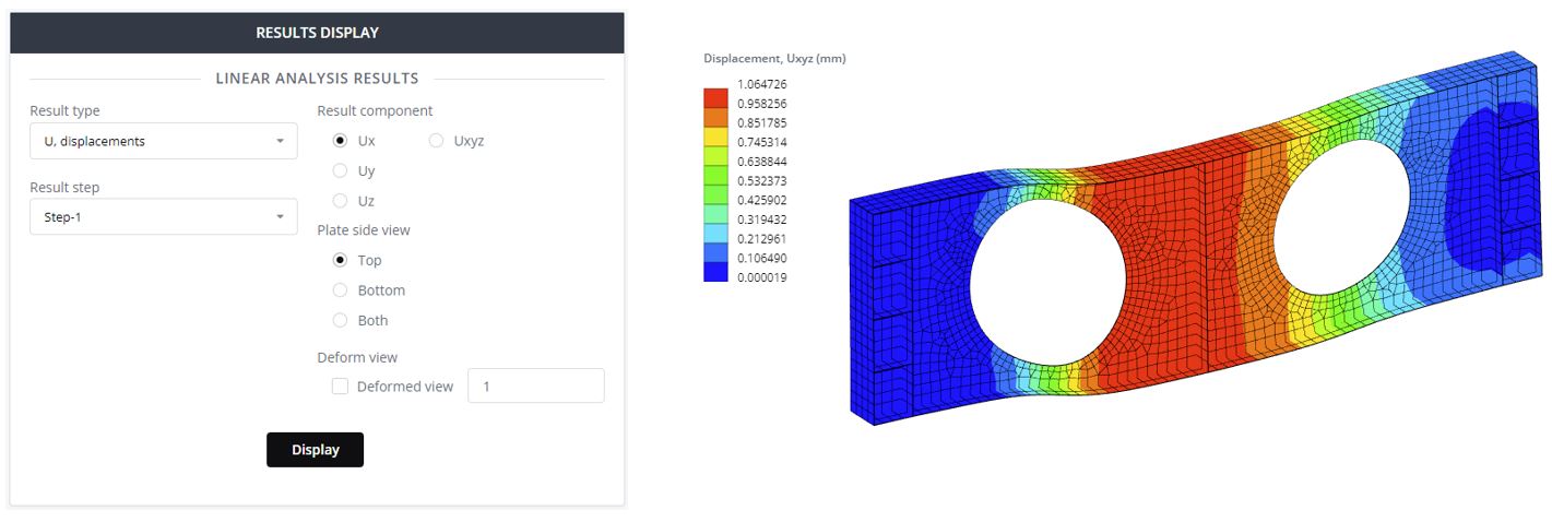
In the Results panel select result type from dropdown list. Display a deformed view of the model with its deformation scaling.
Step 11. Stress Results
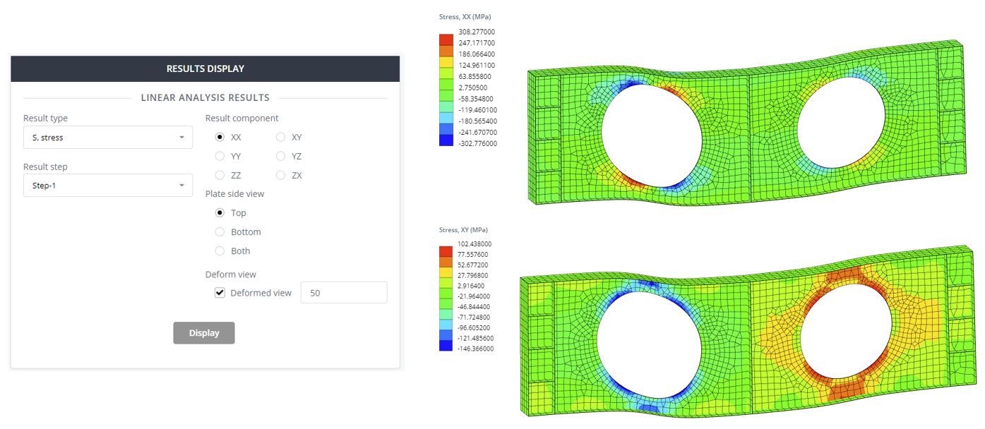
Select Result type ‘S, stress’ to check the stress distribution contour. Select different stress components and display the contour. The normal stress (XX) value is 308 MPa and exceeds the yielding stress of the web 230 MPa. This indicates on the occurrence of plastic strain zones in the web. In the next Tutorial this plasticity will be investigated in more detail for this beam.
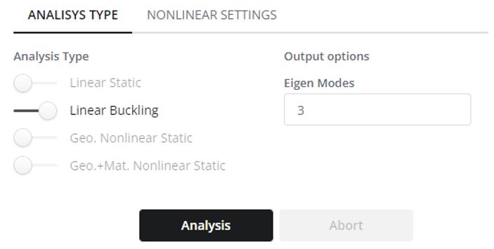
Step 12. Linear Buckling Analysis
Now investigate the linear buckling shapes and critical buckling forces of the beam. Select ‘Linear Buckling’ in the Analysis Type panel. Select the necessary number of buckling shapes, or ‘Eigen Modes’. Typically, for the current type of beam analysis, 3-5 modes is enough. Click the Analysis button.
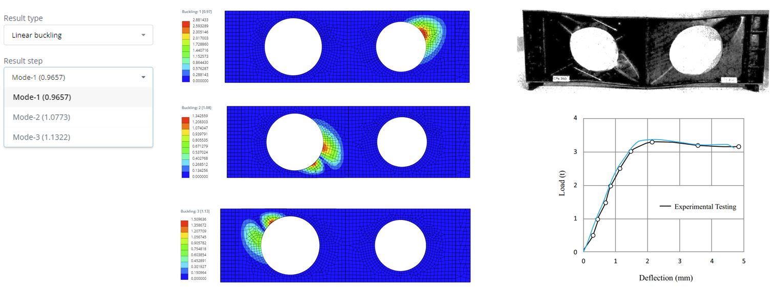
Step 13. Buckling Results
In the Linear buckling results panel you can select the result mode. Here are the 3 modes with their corresponding buckling load factors. If multiply the factor by the applied load value you will receive the critical linear buckling force. For example, with our applied force of 40 kN the critical buckling load will be Fcr = 0.965 x 40 = 38.6 kN. In practice, this means that if apply this critical load to the structure, then the structure becomes unstable in terms of linear buckling stability. The buckling shapes can be seen after clicking on the Display button. Potential buckling shapes are mainly located around the web. This kind of buckling is called as local buckling. Using these results can be confirmed that the structure does not have enough capacity for this applied load. This is also proven by the experimental test results. From the experiment the critical force is below 40 kN.
SkyCiv Beam
Experience fast and precise analysis of beam structures with SkyCiv Beam Software! Try it out now with our Free Beam Tool, equipped with features like bending moment calculator, shear and moment diagram calculator, beam reaction calculator, and much more. Get a taste of what our software can do for you today!