This article is a helpful guide on exporting models from Revit –> S3D using the SkyCiv Plugin, or the File – Import – RVT via the S3D interface. There are a wide array of considerations, but in this guide we’ll focus on the main ones. Namely:
- Make sure there’s an Analytical Model on Revit’s side
- Ensure items are “Structural”
- Properly Connecting Members and Plates
- Defining Sections (Families)
- Defining Materials
- Defining Supports (optional)
- Defining Loads (optional)
- IFC Exporting
- Full List of Required Data
1. Make sure there’s an Analytical Model on Revit’s side
Creating an Analytical Model – Your model should have Analytical Elements in the form of Beams/Plates etc. If Revit doesn’t have Analytical model generated within itself but only has 3D model, then Export will not work correctly. To see if the Revit Model has the Analytical Model associated with it or what is Analytical Model , you can visit following link:
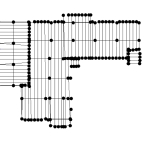
Models come through based on the Revit Analytical Model. So, in the test model, all the Revit analytical elements are imported into SkyCiv with section, materials, nodes, offsets and any other information assigned to these elements. Below is an example:
Revit analytical model:
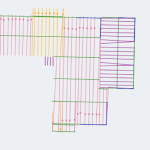
After exporting to S3D:
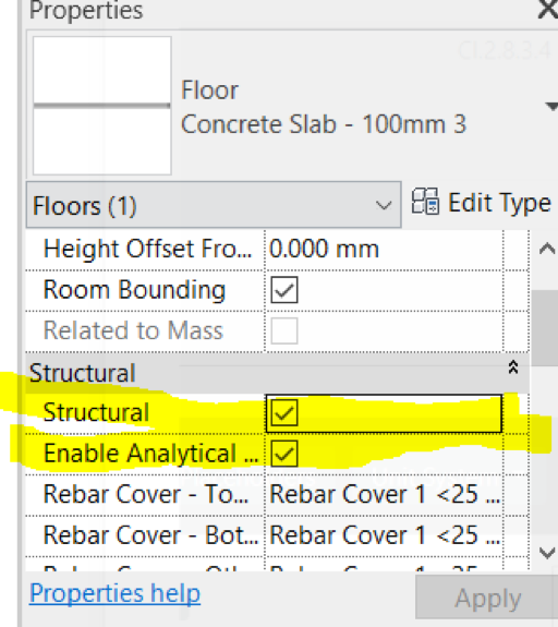
2. Ensure items are “Structural”
This is aligned with the above point. For all the items (Beams/Walls/Columns/Floors), it is necessary to click the Checkbox on “Structural” and “Enable Analytical Model” as shown below:
3. Properly Connect Members and Plates
Another common issue we see on the Revit side, is that members are not connected correctly, or they are built in a way that makes sense for architects, but not necessarily for engineers. When building an accurate Revit model (for structural analysis purposes), the same logic applies – members/plates need to be connected by nodes. Otherwise, the elements are not connected and the results will be inaccurate.
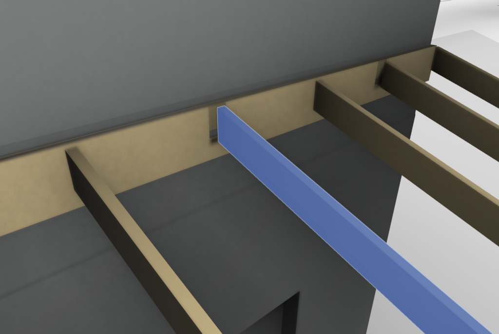
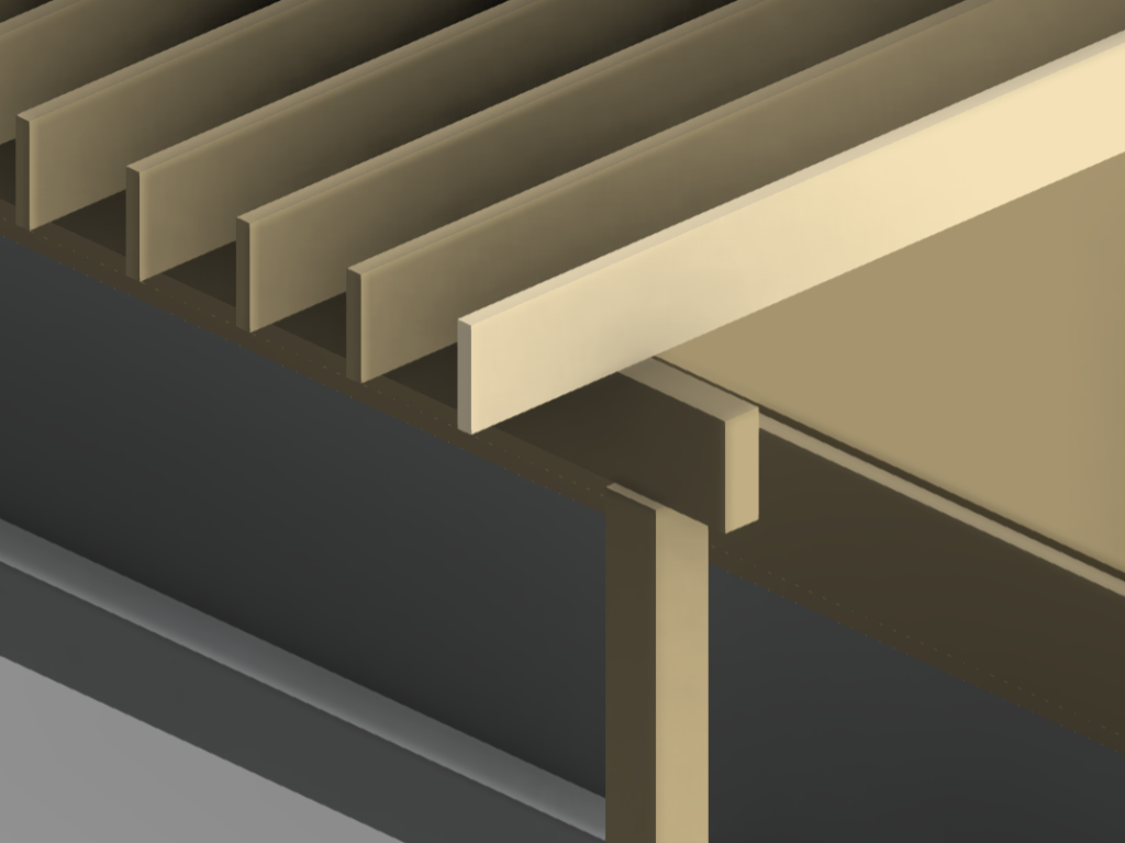
Connectivity is usually the main issue here. For instance, in the following Revit model, there is a disconnect between the highlighted rafter and adjacent beam:
Another common issue is the modeller moving the member by an absolute value, rather than using the Revit offset feature. Offsetting a member will make sure there is still a common node connecting the elements. Below is an example of where this may be the case:
In this case, members are not connected correctly as the rafters have been explicitly positioned above the beam, instead of using the offset members function within Revit:
 Note: in this case, it might be a good idea to split the rafter elements in Revit so the overhang part of the beam is a seperate member.
Connectivity Example
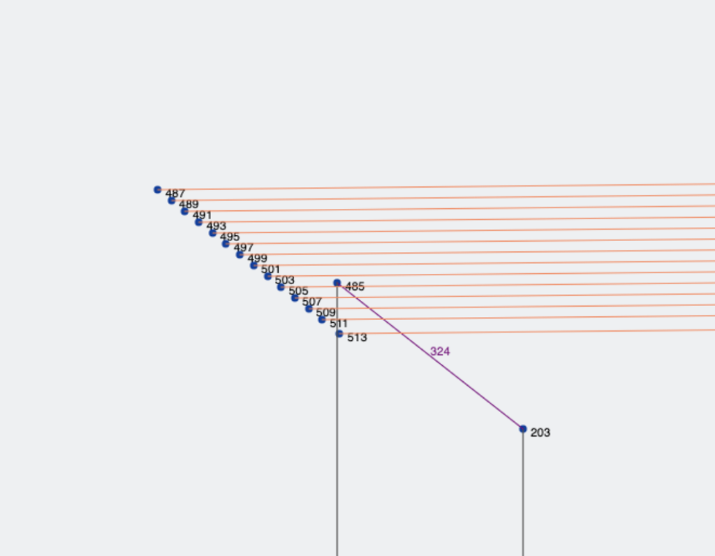
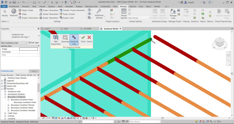
In order to ensure proper connectivity between members, it might help to use an example. The following model, a member is not connected in the analytical model:
The user can simply modify the position of that member so the green member has the same end coordinate as the purple member to fix this connection. Alternatively, users can also use the “Analytical Adjust” feature from Revit. The below step by step guide:
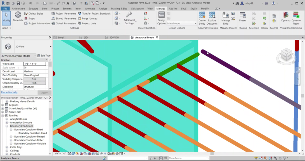
Step 1: Open Adjust Analytical Model in Revit:
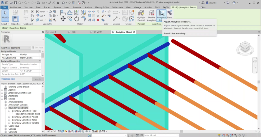
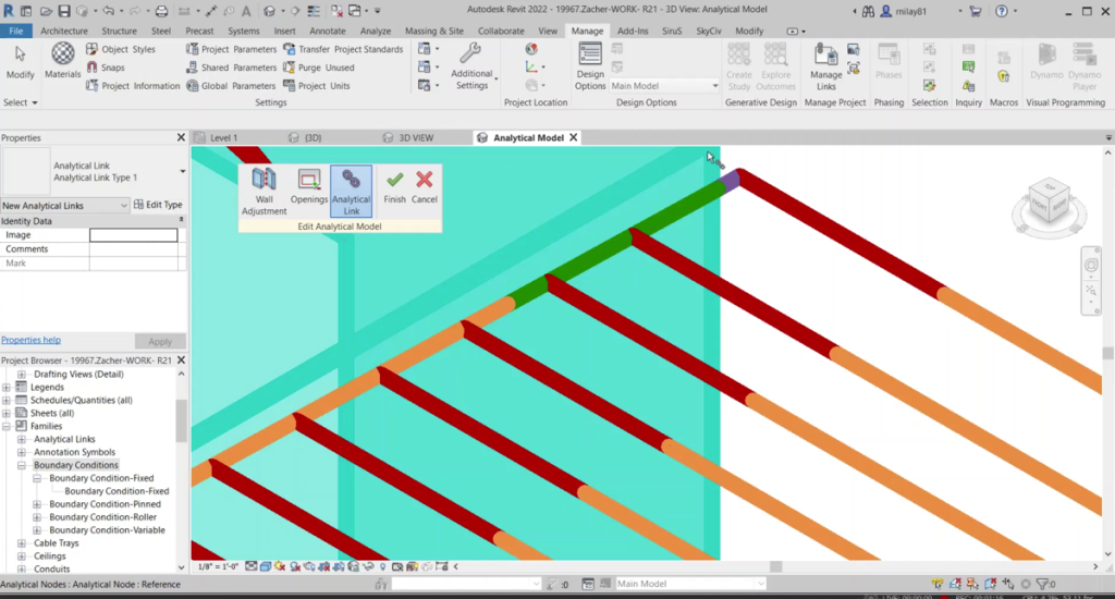
Step 2: Click between the two endpoints to connect via an analytical link:
The members will now be connected via a rigid link:
4. Defining Sections (Families)
If the Revit model has any external custom families associated with it (Structural Framing, columns, beams etc. ), then user needs to declare their properties in the Revit for information like:
- Section Shape
- Structural Dimensions viz. Width, Depth, Thickness etc.
This is required because Plugin tries to find the corresponding section at SkyCiv end by the information given on the Revit side. It first tries to map the sections with the properties provided and if it can’t, then the Plugin will try again with only the name of the Family. If at all it can’t find the mapped SkyCiv Section, it will export with “Not Defined” section so the user can process this on S3D side.
For the standard sections, Revit has the parameters properly defined. But for custom sections, we need to make sure we have attributes/dimensions properly defined. At a high level, the below table will give you the idea about the type of section and the dimensions expected:
| Shape/Sections | Dimensions/Attributes | Revit Name |
| Rectangular Sections | Depth | Height |
| Width | Width | |
| Hollow rectangular Sections | Depth | Height |
| Width | Width | |
| Thickness | WallDesignThickness/
WallNominalThickness |
|
| Outer fillet Radius | OuterFillet | |
| Inner fillet Radius | InnerFillet | |
| Hollow Circular Sections | Depth | Diameter |
| Thickness | Width | |
| I Beam / I Shaped Sections | Top Flange Width | Width |
| Top Flange Thickness | FlangeThickness | |
| Bottom Flange Width | Width | |
| Bottom Flange Thickness | FlangeThickness | |
| Total Height/Depth | Height | |
| Web Thickness | WebThickness | |
| Radius ( if applicable ) | WebFillet | |
| T Beam / T Shaped Sections | Top Flange Width | Width |
| Top Flange Thickness | FlangeThickness | |
| Total Height/Depth | Height | |
| Web Thickness | WebThickness | |
| Radius ( if applicable ) | WebFillet | |
| L Beam / Angle Sections / L Shape | Bottom Flange Width | Width |
| Bottom Thickness | WebThickness | |
| Total Height/Depth | Height | |
| Flange Thickness | FlangeThickness | |
| Radius ( if applicable ) | WebFillet | |
| Channel Sections / C Sections | Top Flange Width | Width |
| Top Flange Thickness | FlangeThickness | |
| Bottom Flange Width | Width | |
| Bottom Flange Thickness | FlangeThickness | |
| Web Thickness | WebThickness | |
| Radius ( if applicable) | WebFillet | |
| Total Height / Depth | Height | |
| Lipped Channel | Total Height/Depth | |
| Top Flange Width | ||
| Top Flange Thickness | FlangeThickness | |
| Bottom Flange Width | ||
| Web Thickness | ||
| Lip Depth | ||
| Radius ( if applicable ) | ||
| Z Shape / Z Section | Total Height | Height |
| Top Flange Width | Width | |
| Bottom Flange Width | BottomFlangeLength | |
| Web Thickness | WallDesignThickness/
WallNominalThickness |
|
| Radius ( if applicable) | InnerFillet |
5. Defining Materials
Revit model should have appropriate material assigned to the Sections. If the material is custom, it should have its mechanical properties correctly defined, including:
- Modulus of Elasticity
- Density
- Poisson’s Ratio
- Yield Strength (for design checks)
- Ultimate Strength (for design checks)
- Other parameters may be required depending on use (Thermal coefficient, shear modulus)
6. Supports + Loads (optional)
Revit Model should have Boundary Conditions (Supports) defined for the respective elements. This is not necessary for the Export functionality but if Boundary conditions are not present, a structural analysis cannot be performed. This information is optional and only necessary if you want to export an analysis-ready model.
For Boundary conditions, we need to follow the below steps:
- First load the family for Boundary Conditions. For loading, please refer to Load Families | Revit 2020 | Autodesk Knowledge Network
- Once you load the families, then you can follow this post for Boundary conditions settings: Boundary Conditions Settings | Revit 2020 | Autodesk Knowledge Network
- The next step would be to assign the Boundary Conditions to respective Column. For this go to “Analytical Model” and follow “Analyze”à “Boundary Conditions” and Select the appropriate node . If you want to change the type of BC , then you can go to “State” dropdown and change the option accordingly.
7. Loads and load combinations:
Following loads can be applied in Revit and transferred over to the following elements (Note: this information is optional and only necessary if you want to export an analysis-ready model)
- Nodes – Point Loads
- Beams – Point load, Uniformly distributed load
- Plates – Pressure Loads
All the Primary load cases declared in the Revit model will be brought as it is in the S3D.
Currently, we don’t support exporting of the load combinations due to difference in the way load combinations are handled in Revit and S3D. But S3D has the capability to automatically generate the load combinations or user can also defined the load combinations after the model is exported to S3D.
8. IFC
As of now, if the model is imported as IFC in Revit, then it will not contain the Analytical Model on Revit’s end. So the export will not include the structural data relevant to your model. This is something that is being improved, so we hope to have this in the future.
9. Full list of required information
There is a lot of data that can be added to your Revit model, but the following should be the bare minimum in order to perform a structural analysis:
- Members
- Section/Family Definition
- Rotation Angle
- Offsets
- End releases
- Plates
- Material
- Thickness
- Materials
- Young’s
- Poissons
- Density
- Others (e.g. Thermal Expansion Coefficient if applying thermal loads)