An Introduction to the Analysis and Design Capabilities of a Bridge Structure for the AISC Student Steel Bridge Competition
Almost year-round, universities around the United States are home to their respective AISC Student Steel Bridge teams and clubs that compete in the AISC Student Steel Bridge competition. This entails an academic year long journey designing and building a model-scale bridge that is tested under various loading conditions and other judging criteria. For the students, this process includes everything from fundraising and preliminary bridge design, to the ordering, fabrication and assembly of the bridge. Sponsored and facilitated by AISC, the Student Steel Bridge Competition gives students a sense of real-world engineering procurement, design and reviewing processes.
A very important aspect of the process – you could say most relevant to post-graduate work – is the analysis and modeling of the bridge structure. Structural engineering software plays an important role by providing students the power to quickly analyze and make decisions on their bridge designs throughout the design process.
SkyCiv Structural 3D gives students the perfect blend of analytical power and adaptability. SkyCiv prides itself on the shortened upstart time it takes to learn the software and operate it effectively, leading to more time adding value to their projects, and sooner too.
With that in mind, lets take look at a preliminary design of a bridge structure for the AISC Student Steel Bridge competition.
Modeling the Truss Structure
Using the bridge envelope constraint documents provided by AISC in the AISC Student Steel Bridge – 2019 Rules, we observe the following:
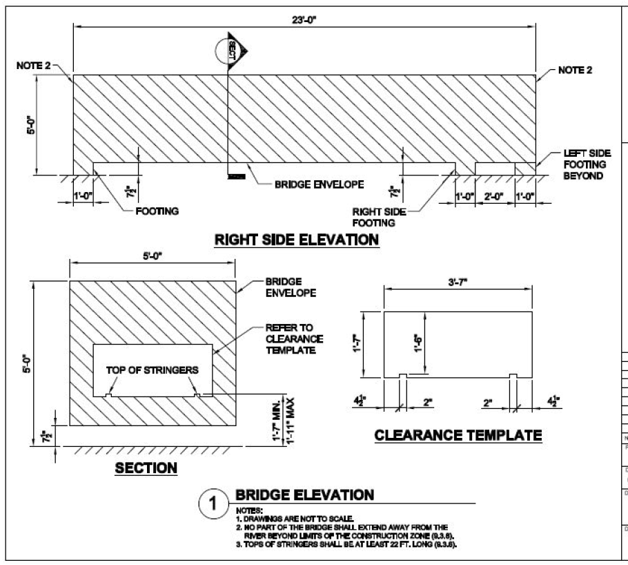
Figure 1: AISC Student Steel Bridge Envelope Drawing
(Source: AISC Student Steel Bridge Competition 2019 Rules)
We will use a Pratt Truss for our example. Click the links for more information about Truss Types and Modeling a Truss. We are going to analyze the stringers as a single member to simplify our model at this stage. More complex stringers can easily be modeled as students move forward in the design process.
Looking at the bridge section, we will assume that ground level is the Y-elevation of 0, and our stringer’s centroid passes through a Y-elevation of 1 foot. Looking at the side elevation, lets assume our supports are centered at each of the 1′-0″ wide footing locations. This would give us a bottom stringer length of 22 feet. For the top stringer of our bridge truss, lets say that its centroid passes through the Y-elevation of 4.75 ft. Finally, we will assume that there are six equal spaces between the ends of our bottom stringers, so our truss connection location spacing is 22 ft/6 = 3.67 ft.
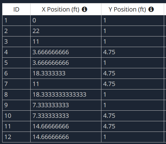
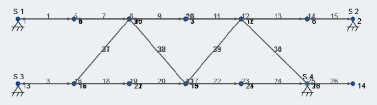
Now that we have the general dimensions our bridge envelope, lets create the nodes. Here’s our node table, with the X-direction being the long dimension for the truss and the Y-direction being the elevation.
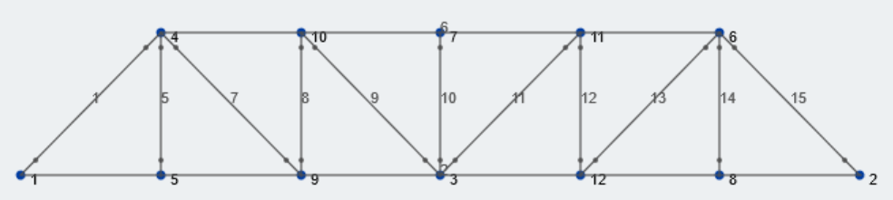
Subsequently, lets draw members between these nodes with the Pratt truss pattern. Make sure to select the “Truss” button on the left window when creating members so that the ends of members are moment-released. Here is our Pratt truss:
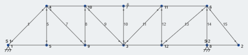
Now lets add some supports. Taking another look at the AISC Bridge Envelope drawing, the right footing is located inward from the end of the bridge, creating a cantilever. To accommodate this, lets move Node 6 and Node 8 to line up with the location of this support; The center of the footing is 3′-0″ inward from the right ride, so our X-dimension will be 19 feet. Finally, lets add pin supports at N0de 1 and Node 8. Take a look at our updated truss:
Next, lets repeat our truss structure across the width of the bridge. This can be done by selecting the entire structure, including nodes and supports, and going to Edit – Duplicate. Looking again at Figure 1, we will assume that the trusses will be centered within each side of the bridge envelope. Therefore, they will be spaced at 4′- 3 1/2″, or 4.22 ft, this is our duplication dimension. We also need to adjust the supports as noted in Figure 1, the left truss has its support at the end of the bridge. After duplicating our truss structure across the lateral axis (Z-axis), our 3D structure now looks like this:
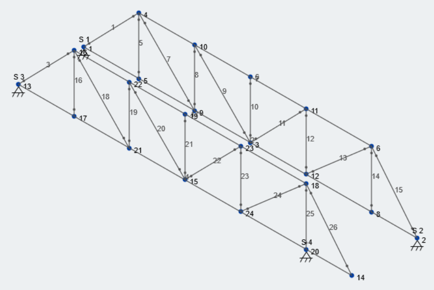
Now, we need to connect our structure using lateral bracing to complete the preliminary modeling of our bridge structure. This portion of the design is somewhat of an iterative process for students; they will try to figure out the correct points to connect each truss together to minimize lateral sway, the main metric judged during the Lateral Load Case. Lets put in some diagonal reinforcement between the top and bottom stringers of the trusses. For example, as shown from the top view:
Modeling in SkyCiv’s Structural 3D module is extremely intuitive and leads to quicker analysis and simpler results. Give your students a try modeling a truss in 2D using our Free Truss Design Calculator tool.
Applying Loads to our Bridge
After modeling, now we can start to apply the loads set by AISC. There are two load types of loads, or load cases, that the bridge will be tested on: Lateral and Vertical. The magnitudes of each load case are given by AISC, but their exact location along the bridge length is not. Therefore, students will need to analyze multiple different locations for each load case to find out the worst case scenario for each. It should be noted that each load case is applied independently; the structure does not see both loading situations at the same time.
Because the loads that are supplied by AISC are ACTUAL loads that will be used in the competition, we can assume they are service loads. We are trying to design this bridge the lightest we can while still meeting the deflection criteria. therefore, our Load Combinations will not include any amplifying load factors.
Lateral Load Case
For the Lateral Load Case, lets look at the load drawing supplied by AISC in the 2019 Rules (Figure 2):
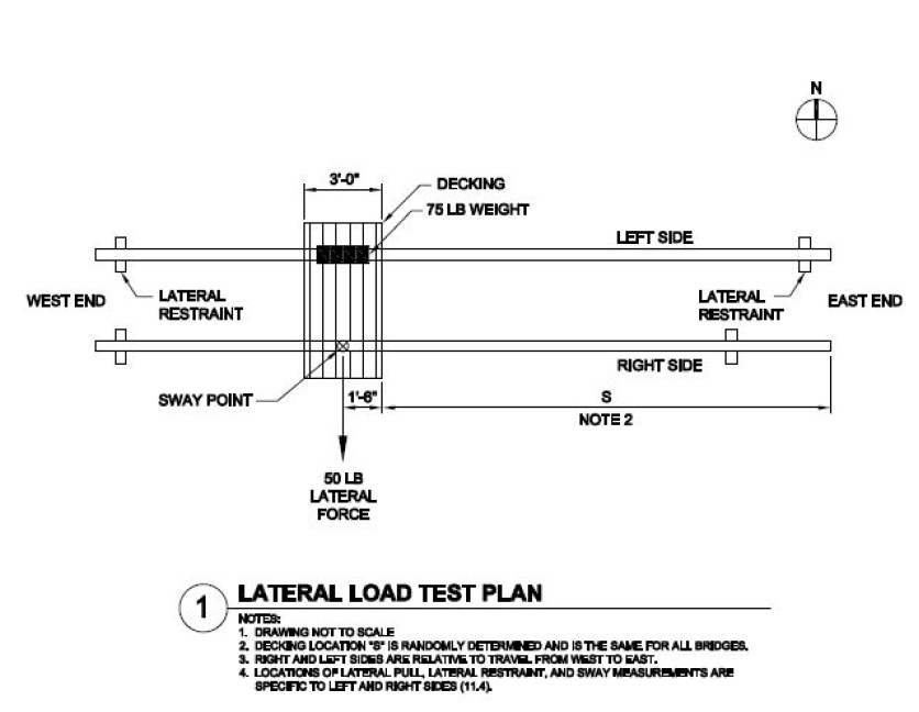
Figure 2: Lateral Load Test Plan for AISC Student Steel Bridge Competition
(Source: AISC Student Steel Bridge Competition 2019 Rules)
First, you notice that not only is there a 50 pound lateral force on the ride side, but there is a 75 pound vertical load on the left side at the same relative location along the bridge length. Second, Note 2 states that the location “S” is randomly determined. During testing, AISC using metal grating/decking to support the weight as well as an anchor point for the lateral force:
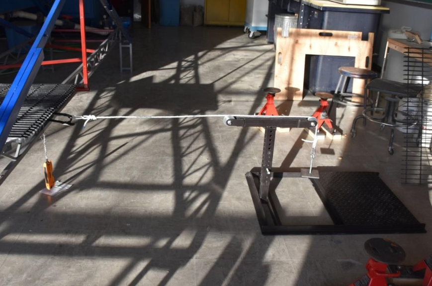
Source: AISC Competition Guide for Participants
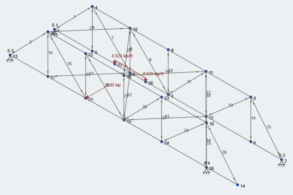
For this example, we will apply the 50 lb lateral load on the “Node 21″ of our model. The 75 lb vertical load on the opposite side will be applied as a uniform distributed load over the 3′-0” width of decking.
\(Lateral\:Load = 50\:lb = 0.05\:kip\)
\(Vertical\:Load=75\:lb/3\:ft = 25\:lb/ft = 0.025\:kip/ft\)
As mentioned earlier, these are service loads, so both of these loads will occur under the load case we created called “Lateral Load Case” and will be considered Live Load. The subsequent load combination will be LC #1 and is as follows:
\(LC\:1=1.0*Self\:Weight\:of\:Structure + 1.0*Lateral\:Load\:Case\)
Again, students will need to apply the lateral and vertical load at multiple locations along the bridge length to figure out the location that gives the governing analysis results. Here is how our model looks will these loads applied:
Vertical Load Case
For the Vertical Load Case, lets look at the load drawing supplied by AISC in the 2019 Rules (Figure 2):
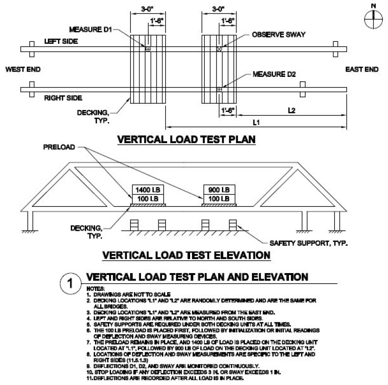
Figure 3: Vertical Load Test Plan for AISC Student Steel Bridge Competition
(Source: AISC Student Steel Bridge Competition 2019 Rules)
Similar to the lateral load case, the locations that the vertical loads act are not directly indicated. This time, there are two separate loading cases that we need to evaluate. First, there is the 100 lb pre-loading condition. Then, the additional 1400 and 900 lbs are added to equate to a 1500 and 1000 lb load respectively, as shown in Figure 3. We will assume that the loads are carried evenly between the trusses, and that they act as a uniform distributed load over the length of the decking. Also, we will identify all of the vertical loads as Live Load.
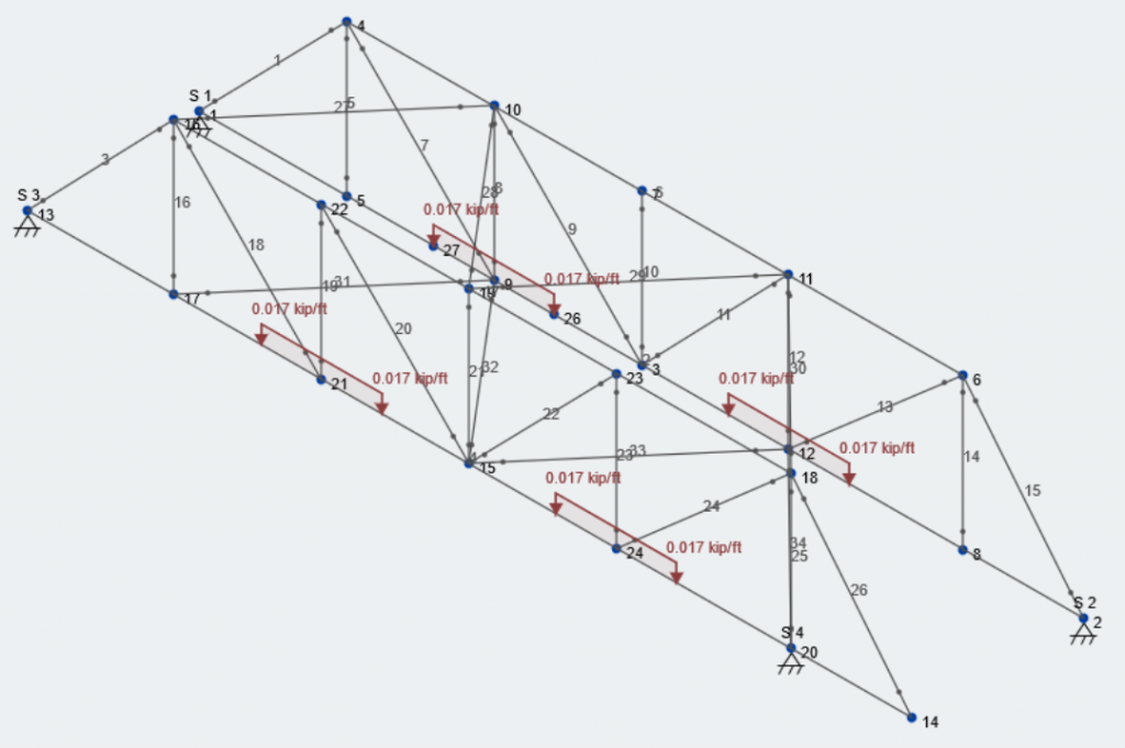
The pre-loading will be its own load case and will be called “Vertical Load Case – Pre-load”. Lets apply the distributed loads centered at Node 21/9 and Node 24/12. Node 24 and 12 are mirrored across the center of the bridge.
\(Preload = (100\:lb/2)/3\:ft = 16.7\:lb/ft = 0.0167\:lb/ft\)
Subsequently, the load combination being:
\(LC\:2=1.0*Self\:Weight\:of\:Structure + 1.0*Vertical\:Load\:Case-Preload\)
Here is what our model looks like with the preloading case:
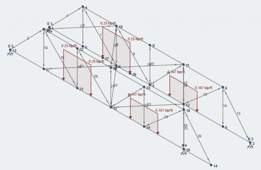
Now, lets add the remaining load. On the left side the total load is now 1500 lb, and on the right side there is now 1000 lb. We will save this as another load case called “Vertical Load Case – Total”.
\(Total\:Load\:on\:Left\:Side\: = (1500\:lb/2)/3\:ft = 250\:lb/ft = 0.25\:kip/ft\)
\(Total\:Load\:on\:Right\:Side\: = (1000\:lb/2)/3\:ft = 167\:lb/ft = 0.167\:kip/ft\)
Our last load combination is therefore identified as:
\(LC\:3=1.0*Self\:Weight\:of\:Structure + 1.0*Vertical\:Load\:Total\)
Here is what our model looks like with the total load applied in the vertical load case:
See the below for a picture of a recent competition and the loading mechanism for the vertical load case:
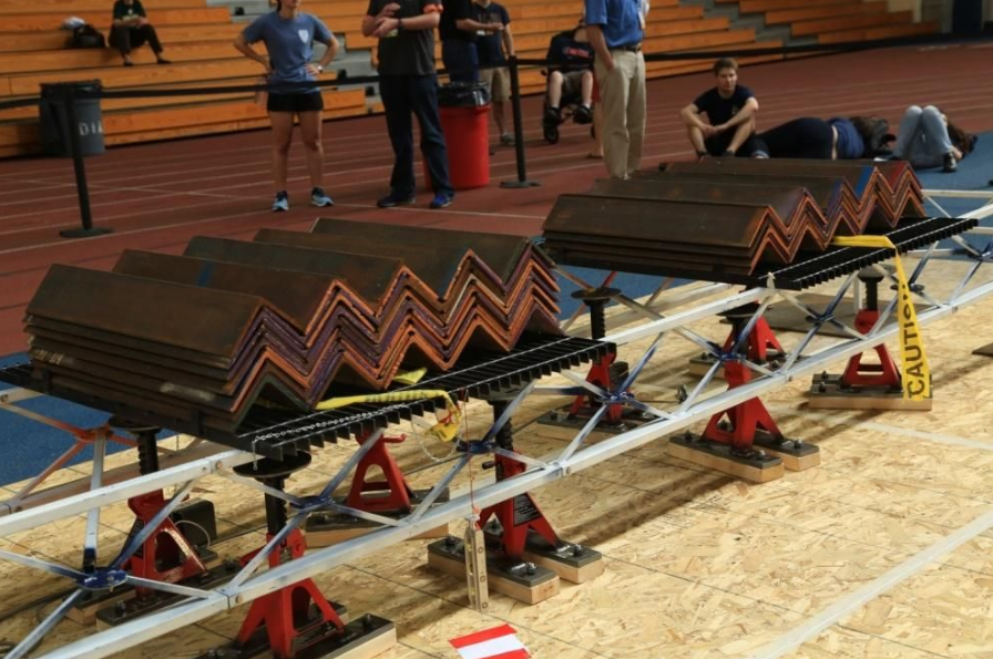
Source: AISC Competition Guide for Participants
Analysis of Load Cases/Combinations
The last portion of this exercise is running the analysis on our bridge structure and interpreting the results. Before we do that, lets take a look at the load combinations and their load factors:

These loads are service loads, so we will be using a load factor of 1.0 on all of them. These three load combinations encapsulate the loading conditions presented between the Lateral Load Case and Vertical Load Case, provided by AISC. Now, lets run our analysis. For practical purposes, we will look at the axial results for the right truss with the cantilevered end for LC 3.
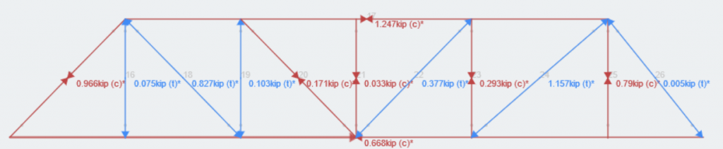
SkyCiv gives the users power to hide, isolate and view their structures results in whatever way they see fit. Look at the entire structure for a more global idea, or isolate combinations or single members to evaluate on a more granular level. From here, students will need to go through the iterative design and collaboration process with their team. Students can now focus on becoming better and well-prepared engineers for not only the AISC Student Steel Bridge competition, but as an Engineer-in-Training and Professional Engineer.
This example shows how powerful yet simple SkyCiv 3D can be, with its intuitive modules aimed towards users ranging from first year engineering students to principal engineers at the height of their careers. SkyCiv hopes that it can be a prominent tool for use within the classroom, allowing students to focus on learning about engineering rather than learning about the software.
References:
- “University Programs.” AISC, 2019, www.aisc.org/education/university-programs/student-steel-bridge-competition/.