Beam Behaviour: Moment Capacity of a Beam
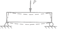
Before discussing the moment capacity calculation, let us review the behavior of a reinforced concrete simple beam as the load on the beam increases from zero to the magnitude that would cause failure. The beam will be subjected to downward loading, which will cause a positive moment in the beam. The steel reinforcing is located near the bottom of the beam, which is the tension side. Here we may select three major behavior modes of beam:
1. Flexural behavior at a very small load
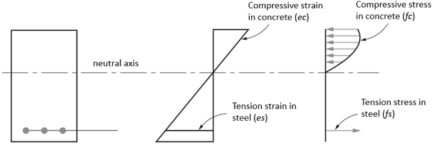
Assuming that the concrete is not cracked and steel will resist the tension. Also concrete at the top will resist compression. The stress distribution will be linear:
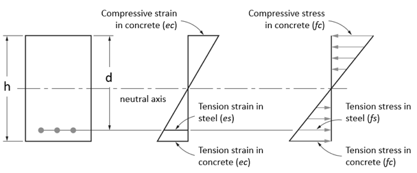
2. Flexural behavior at moderate load
In this case, tensile strength of the concrete will be exceeded, and the concrete will crack in the tension zone. Because the concrete cannot transmit any tension across a crack, the steel bars will then resist the entire tension The concrete compressive stress distribution is still assumed to be linear.
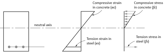
3. Flexural behavior at ultimate load
Here the compressive strains and stresses are increased, with some nonlinear stress curves on the compression side of the beam. This stress curve above the neutral axis will be essentially the same shape as the typical concrete stress-strain curve. Tension steel stress fs is equal to yield stress of steel fy. Eventually, the ultimate capacity of the beam will be reached and the beam will fail.
- Strain in concrete is the same as in reinforcing bars at the same level, provided that the bond between the steel and concrete is adequate;
- Strain in concrete is linearly proportional to the distance from the neutral axis
- Plane cross-sections continue to be plane after bending
- The tensile strength of concrete is neglected
- At failure, the maximum strain at the extreme compression fibers is assumed to equal to limited by the design code provision (0.003)
- For design strength, the shape of the compressive concrete stress distribution may be simplified.
Assumptions
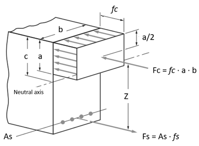
The determination of the moment strength is not simple because of the shape of the nonlinear compressive stress diagram above the neutral axis. For purposes of simplification and practical application, a fictitious but equivalent rectangular concrete stress distribution was proposed by Whitney and subsequently adopted by the different design codes, like ACI 318, EN 2, AS 3600, and others. With respect to this equivalent stress distribution as shown below, the average stress intensity is taken as fc(at ultimate load) and is assumed to act over the upper area of the beam cross-section defined by the width b and a depth of a. In different design code parameters, a is determined by reducing c with factor. Concrete strength fc is reduced as well. For example, according to the ACI 318 code fc is reduced by 0.85 and a by β1 factor that is between 0.65 and 0.85.
Calculate the Neutral Axis Depth
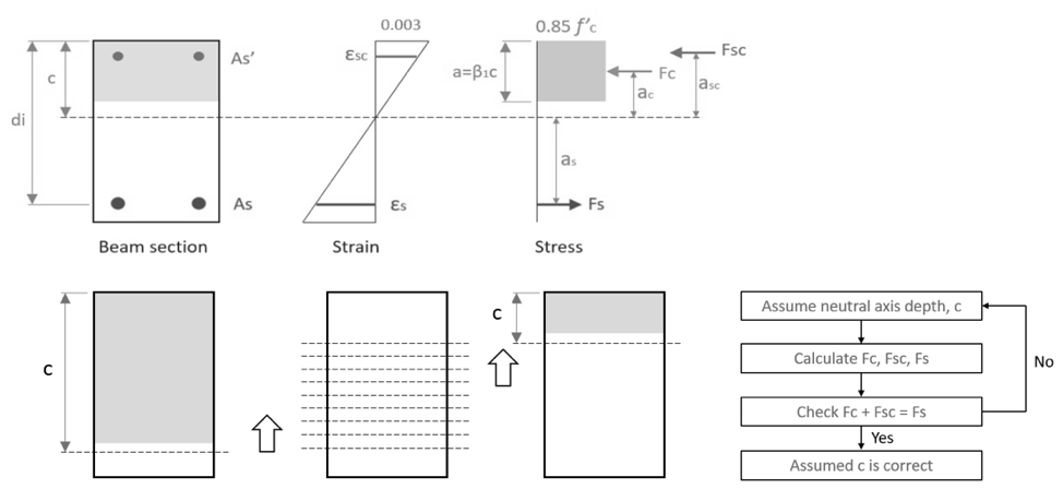
To calculate the moment resistance capacity of the reinforced concrete section it’s necessary to calculate the neutral axis depth c correctly. SkyCiv uses an iterative process to calculate the neutral axis based on the following:
Calculate the Moment Capacity
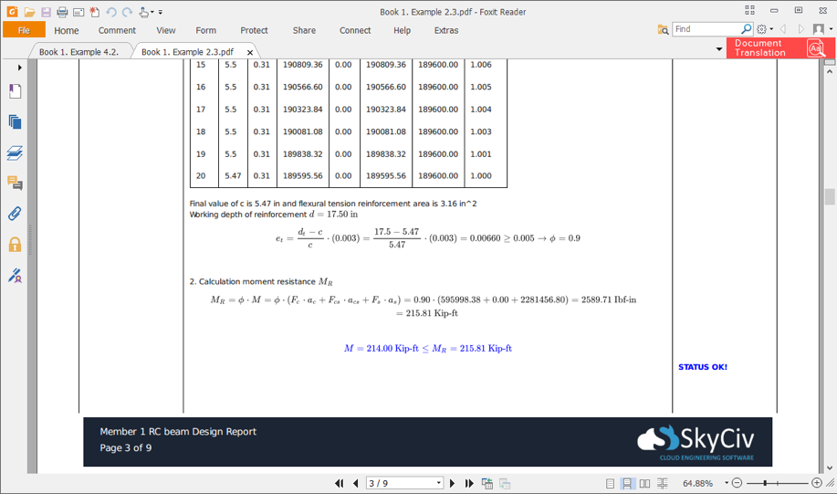
Finally the calculated concrete and steel forces Fc, Fs, Fcs and their position from the section neutral axis ac, as, acs allow to calculate the design moment resistance from the following equation:
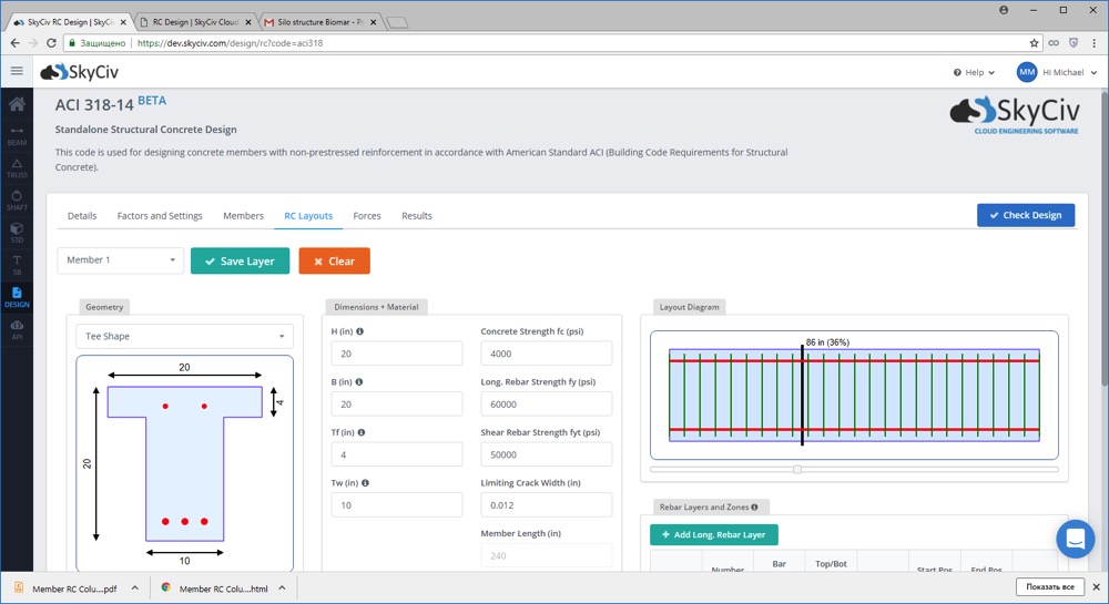
All this procedure is totally automated in SkyCiv Reinforced Design Software, where an engineer can easily define reinforced concrete beams with acting loads and determine the capacity of the section. This and all other design check calculations can be seen in the detailed design report that is generated by SkyCiv after analysis.
SkyCiv Reinforced Concrete Design
SkyCiv offers a fully featured Reinforced Concrete Design software that allows you to check concrete beam and concrete column designs as per ACI 318, AS 3600, and EN2 Design Standards. The software is easy-to-use and fully cloud-based; requiring no installation or downloading to get started!
For more beam analysis solutions, check out our SkyCiv Beam – integrated into the SkyCiv Structural 3D with the Reinforced Concrete Design. Or test it out now with our Free Beam Solver!