National Design Specification Standards® for Wood Construction 2018 Edition (NDS 2018)
The National Design Specification® standards for Wood Construction (ANSI/AWC NDS-2018) incorporate design provisions for both allowable stress design (ASD) and load and resistance factor design (LRFD). This specification is adopted in all model building codes in the United States.
The SkyCiv timber design module performs all cross-section resistance designs, stability analyses, and deformation analyses provided by the standard. In timber construction, the serviceability limit state represents an important design. The conservative limit deformation is present but can be modified, if necessary.
This module is one of the many design modules integrated into the S3D environment. Thus, the design-relevant input data is preset when you open the module. Also you can use standalone Design Software.
This documentation applies to NDS 2018 Edition in either ASD or LRFD provision. Learn more about SkyCiv’s timber design module below, or at the design code page: NDS® standards Wood Design.
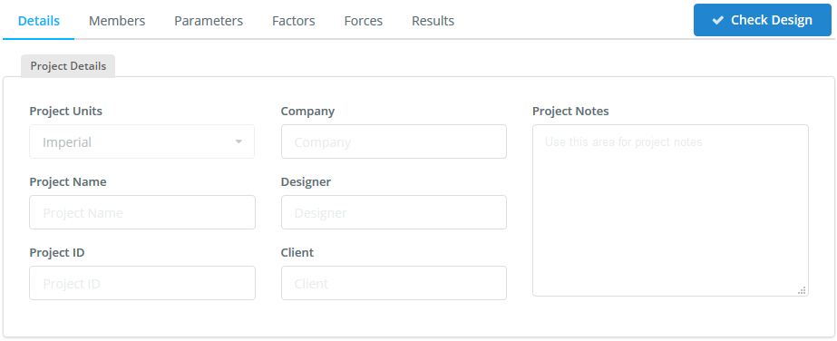
Details
Once you have chosen either ASD or LRFD you will be presented with the Details tab as shown in the figure below. The units will be chosen automatically by program as imperial.
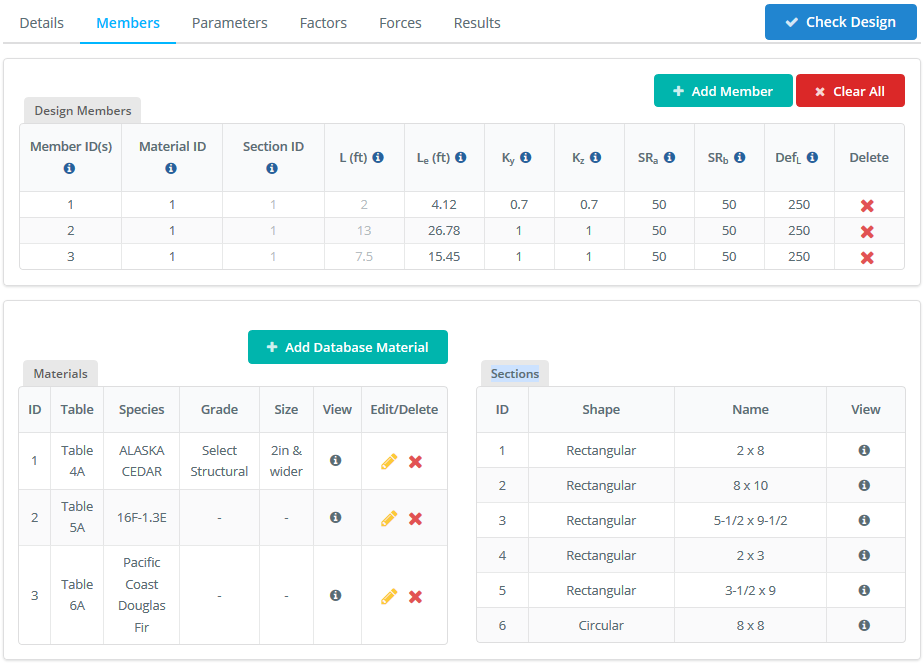
Members
The Members tab contains all the input related to the each of the members to be designed in the module. These may contain specific parameters for each design software (hover over the tooltips for more info). These can be changed at anytime by changing the values in the cells.
Design Members
The Design Member table contains all the members, their materials, section IDs, length and their limit factors that have been automatically populated from the model. You can also delete certain members that you don’t want to include in the design check.
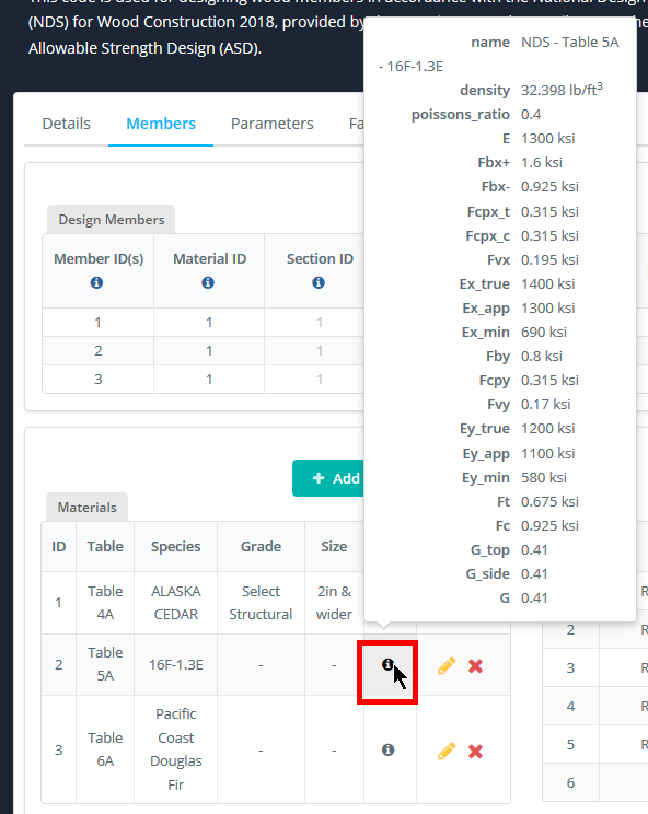
The materials and Sections (in the lower tables) are automatically populated from the model. You can hover over the icon for more information.
-
- Member ID(s) – Member(s) from your model that make up the design member.
-
- Material ID – The Material ID of the design member from the Material Table. It can be modified.
-
- Section ID – The Section ID of the design member from the Section Table below.
-
- L (ft) – The total length of the design member.
-
- Le (ft) – Effective Length for Bending (Table 3.3.3). By default, this is 2.06L as it is the most conservative value. It can be modified.
-
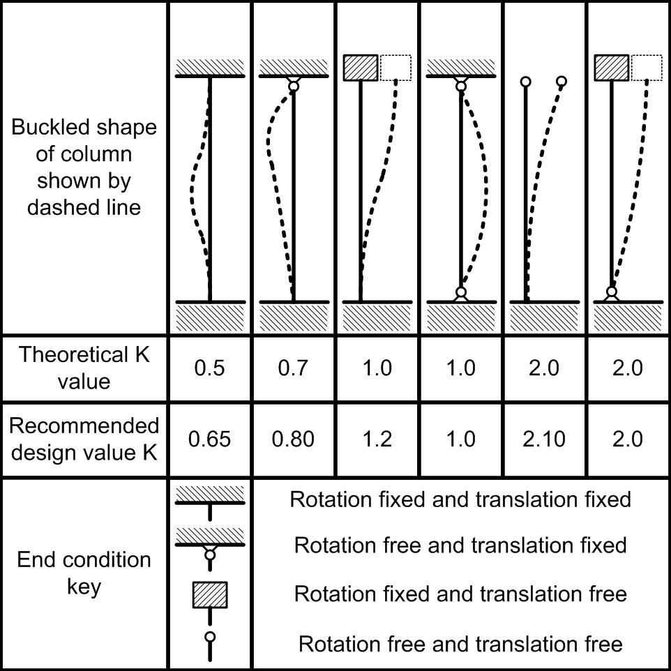
- Ky and Kz – Effective Length factors for flexural buckling about y-axis and z-axis. It is calculated automatically but it can be modified.
-
- SRa – Slenderness ratio for Axial. The default value equals 50 it is taken from NDS 2018 (3.7.1.3). It can be modified.
-
- SRb – Slenderness ratio for Bending. The default value equals 50 it is taken from NDS 2018 (3.3.3.7). It can be modified.
-
- DefL – Deflection limit ratio. It can be modified.
Materials
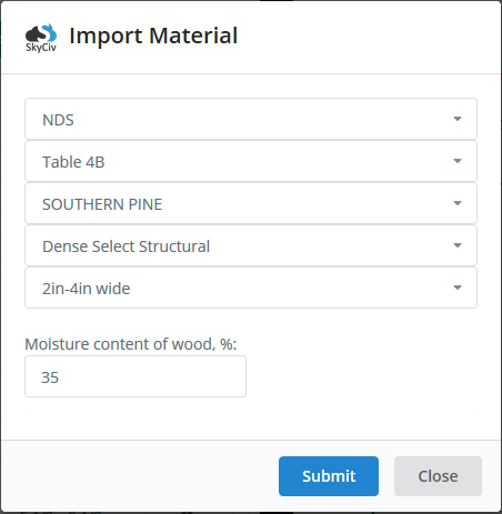
The materials defined in S3D are preset, but you can always add the new: for that click + Add Database Material to open the material list.
According to the design concept of AWC NDS-2018 and its Supplement, the list includes only materials of the U.S. standard.
If you add the material description manually and used this material for design then you have to add this material in the S3D too.
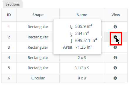
Sections
This table shoves the cross-sections used for design. The cross-sections defined in S3D are present in this table.
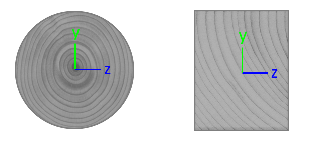
The design is possible for the parametric round cross-section and for the standardized timber rectangular cross-section according to NDS-2018 Supplement.
Parameters
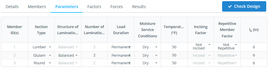
The Parameters tab contains all the input related to the each of the members to be designed in the module. The module uses these parameters for automatic calculation of Adjustment Factors. These can be changed at anytime by changing the values in the cells.
-
- Member ID(s) – Member(s) from the Members tab.
-
- Section Type – This parameter is defined automatically. It can get three values Lumber (Sawn lumber), Glulam (Structural glued laminated timber) and Round (Round timber poles and piles).
-
- Structure of Laminations – This parameter needs for determining the reference bending design values Fb for structural glued laminated timber. See NDS 2018 (5.2.3).
-
- Number of Laminations – This parameter needs for determining the reference bending design values for structural glued laminated timber. See NDS 2018 Supplement (Table 5B and Table 5D).
-
- Load Duration – This parameter needs for determining the adjustment factor CD(Load duration factor). See NDS 2018 (2.3.2).
-
- Moisture Service Conditions – The determination of moisture conditions makes it possible to assign the wet service factors CM to each member. The moisture service conditions can be specified individually for each material according to NDS 2018 and Supplement. By default, the program assigns dry service condition.If you want to allocate different moisture conditions to specific members, use the lists.
-
- Temperature (°F) – The determination of temperature service conditions makes it possible to assign the temperature factors CT to each member. The temperature conditions according to NDS 2018 (2.3.3). By default, the program assigns temperatures 50 °F.
-
- Incising Factor – For sawn lumber members, you can determine whether the Incising Factor Cii are to be applied in the calculation or not. See NDS 2018 (4.3.8)
-
- Repetitive Member Factor – For sawn lumber members, you can determine whether the Repetitive Factor Cr are to be applied in the calculation or not. See NDS 2018 (4.3.9)
-
- lb (in) – The determination of length Lb makes it possible to assign the bearing area factors Cb to each member. The length Lb according to NDS 2018 (3.10.4). By default, the program assigns length 6″.
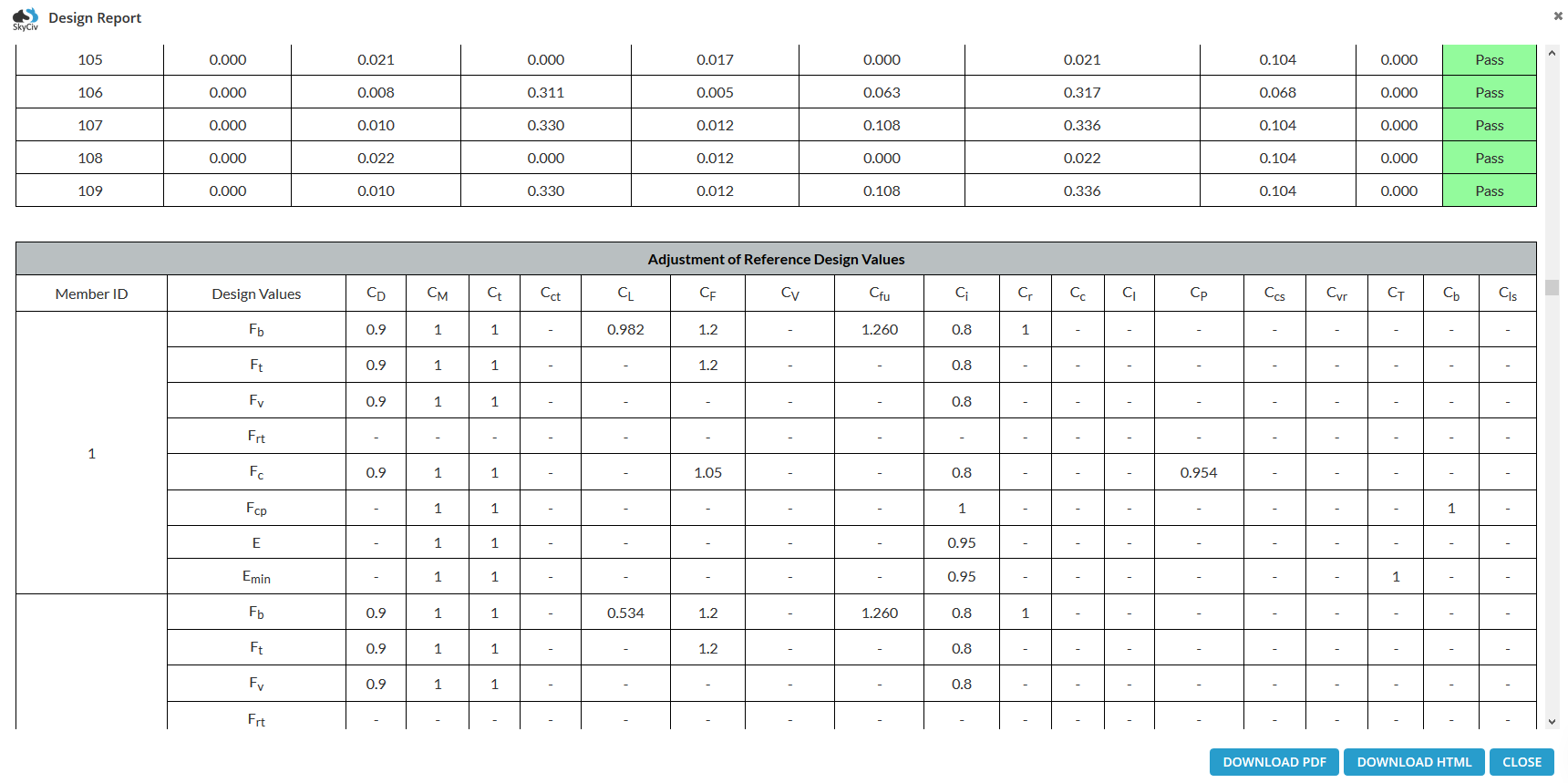
Factors
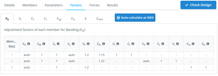
The Parameters tab contains all the input related to the each of the members to be designed in the module. The module uses these parameters for automatic calculation of Adjustment Factors. These can be changed at anytime by changing the values in the cells.
-
- CD – Load Duration Factor (ASD only) in accordance NDS 2018 (2.3.2). The parameter can be defined automatically.
-
- CM – Wet Service Factor in accordance NDS 2018 (4.3.3, 5.3.3, 6.3.3). The parameter can be defined automatically.
-
- Ct – Temperature Factor in accordance NDS 2018 (2.3.3). The parameter can be defined automatically.
-
- CL – Beam Stability Factor in accordance NDS 2018 (3.3.3.8). The parameter can be defined automatically.
-
- CF – Size Factor in accordance NDS 2018 (4.3.6). The parameter can be defined automatically.
-
- CV – Volume Factor in accordance NDS 2018 (5.3.6). The parameter can be defined automatically.
-
- Cfu – Flat Use Factor in accordance NDS 2018 (4.3.7, 5.3.7). The parameter can be defined automatically.
-
- Ci – Incising Factor in accordance NDS 2018 (4.3.8). The parameter can be defined automatically.
-
- Cr – Repetitive Member Factor in accordance NDS 2018 (4.3.9). The parameter can be defined automatically.
-
- Cc – Curvature Factor in accordance NDS 2018 (5.3.8). At the moment the module unsupported to design the curved members.
-
- CI – Stress Interaction Factor in accordance NDS 2018 (5.3.9). At the moment the module unsupported to design the tapered members.
-
- Cvr – Shear Reduction Factor in accordance NDS 2018 (5.3.10). The parameter is defined by user.
-
- Cct – Condition Treatment Factor in accordance NDS 2018 (6.3.5). The parameter is defined by user.
-
- Ccs – Critical Section Factor in accordance NDS 2018 (6.3.9). The parameter is defined by user.
-
- Cls – Load Sharing Factor in accordance NDS 2018 (6.3.11). The parameter is defined by user.
-
- CP – Column Stability Factor in accordance NDS 2018 (3.7.1). The parameter can be defined automatically.
-
- CT – Buckling Stiffness Factor in accordance NDS 2018 (4.3.11, ). The parameter can be defined automatically.
-
- Cb – Bearing Area Factor in accordance NDS 2018 (3.10.4). The parameter can be defined automatically.
-
- KF – Format Conversion Factor (LRFD Only) in accordance NDS 2018 (2.3.5). The parameter can be defined automatically.
-
- φ – Resistance Factor (LRFD Only) in accordance NDS 2018 (2.3.6). The parameter can be defined automatically.
-
- λ – Time Effect Factor(LRFD Only) in accordance NDS 2018 (2.3.7). The parameter is defined by user.
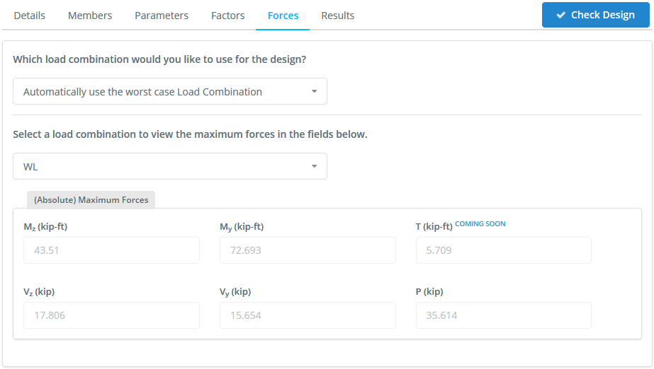
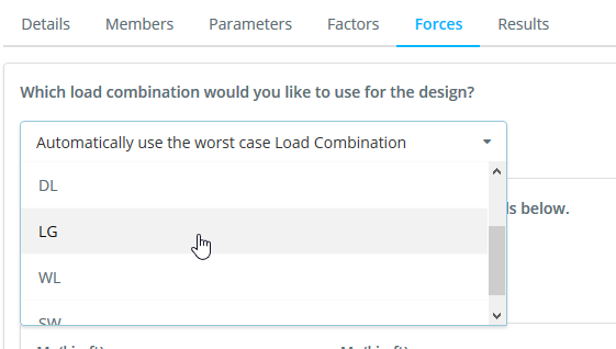
Forces
Internal member forces are automatically imported from the structural analysis, this includes load combinations. The software will display each of the forces as per the selected load combination. The software will design check based on the worst case for each member and load combination.
Results
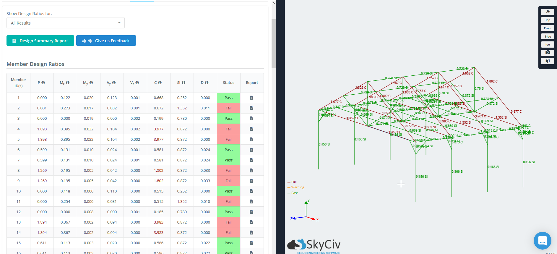
There are three ways to review the results of your design check:
- Tabulated Results – these will highlight the members as Pass or Fail in green or red, respectively.
- Graphical Results – on the right side, the structure will display the green and red colouring of each member as well as the highest capacity ratio of all the results. For instance, if the max capacity ratio is 1.321 for Slenderness, it will display 1.321 Sl – it will display as red as the ratio is > 1. Warning ratios of > 0.95 but < 1 will display in orange, while green indicate the maximum member capacity ratio is < 1. A grey member will indicate that a design check was not performed on this member. You can also select specific design ratios, by changing the dropdown list of “Show Design Ratios for:” – this will show All Results (maximum capacity ratio) by default.
- Reporting – You can export a PDF summary report of the design checks at anytime.