Example Overview
In this advanced example you will continue to investigate the behavior of the previous beam, but now in terms of nonlinear static analysis.
The linear static and linear buckling analysis performed previously allows to quickly analyze and optimize the structure. However, sometimes it is necessary to see the ‘real picture’ of the failure. See how plasticity is distributed in the elements, what the values and how the geometric imperfection affects on the buckling.
In order to see this final picture of failure the nonlinear static analysis must be considered. This analysis considers external loads by portions (or steps), where the material and geometric nonlinearity considered to determine the stress-deformed shape at each step.
Step 1. Mesh Refinement
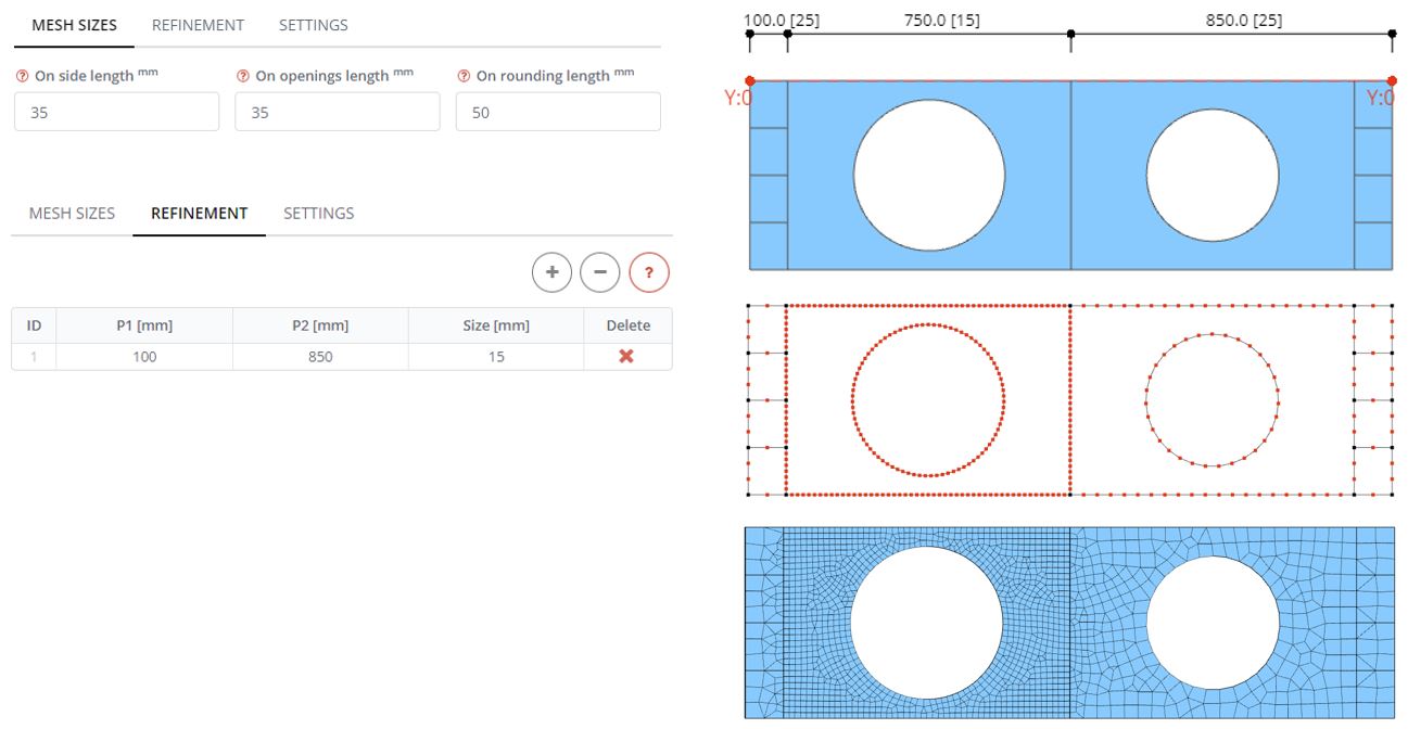
In the Mesh panel define the mesh size for all edges and openings 35 mm, making the global model mesh more coarse than it was previously. Then go to the Refinement tab. Define row in the table and the mesh refinement zone starting from (P1) 100 mm and ending (P2) at 850 mm from the beginning of the beam. The mesh size in this zone is 15 mm. Generate the mesh for the model and observe how the more dense mesh is created in the first web panel.
Step 2. Nonlinear Material Properties
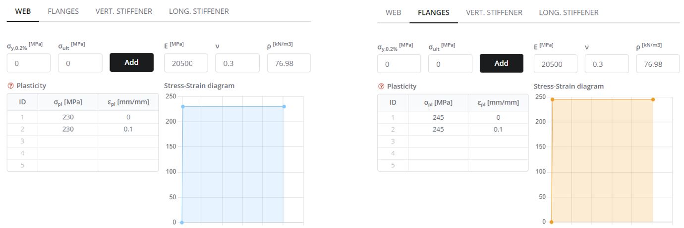
In the Materials panel define plastic stress and strain properties of the materials. Beam parts are made of steel with yielding stress values of 230 MPa for the web and 245 MPa for other components.
Define a bi-linear diagram that includes two zones: linear and plastic. First set Modulus of Elasticity (E) for steel. In the second row of the table create ‘plastic’ zone with the same value of plastic stress Repeat this procedure for the other beam components like the flanges and stiffeners with the plastic stress of 245 MPa.
Step 3. Web Imperfections
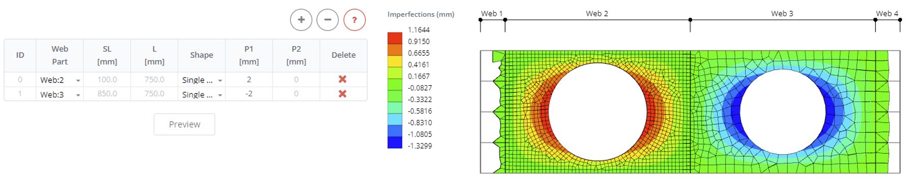
Define imperfections to web panels 2 and 3. Define two rows and select web panels. Define the direction of imperfection and magnitude (P1) as 2 mm for the one panel and -2 mm for another panel. Click the Preview button to see how it affects on the FE model geometry during the analysis.
Step 4. Displacement Load
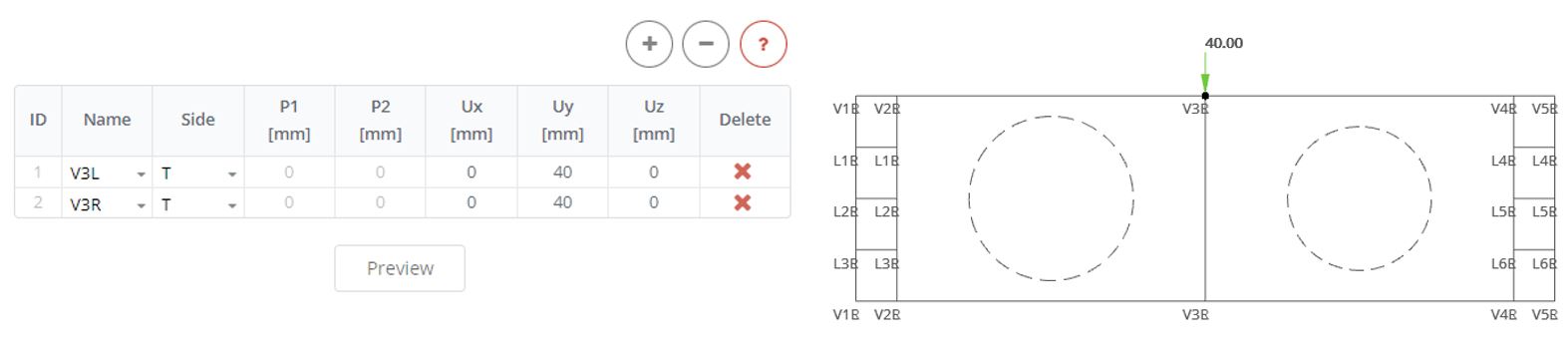
Remove previously defined forces from the stiffeners. Then in the Displacement Stiffeners panel apply a displacement load along the y-axis of 40 mm.
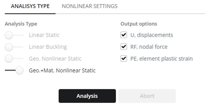
Step 5. Nonlinear Analysis
In the Analysis panel select the Geometry and Material Nonlinear Static Analysis Type. Click the Analysis button.
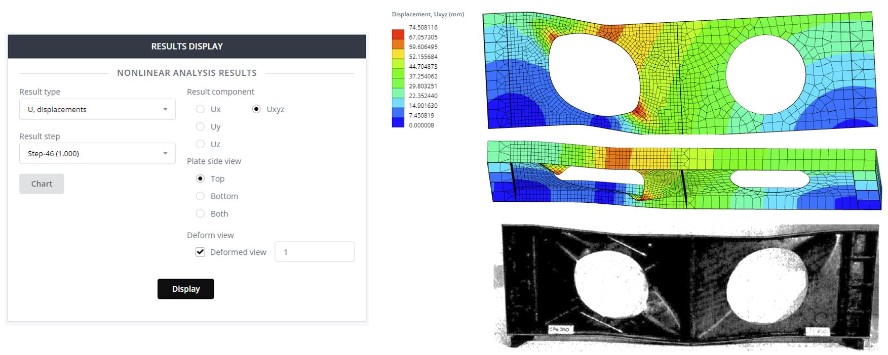
Step 6. Displacement results
In the Result Step select the final step (1.0). Select the displacement component and include the deformed view with a scale of 1.
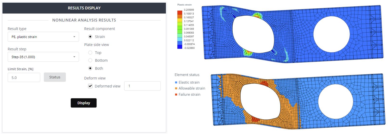
Step 7. Plasticity Results
Select Plate side view both and click Display to see the plastic strain contour plot. Here, a value of zero means that the element has no plasticity. Define in the Limit Strain field 5% and click the Status button. As a result, you will see the safe and unsafe zones of the structure.
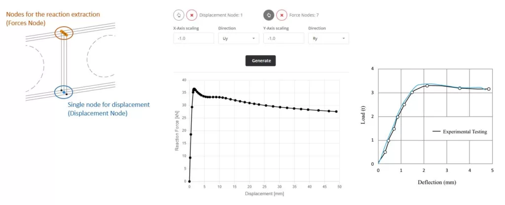
Step 8. Load-Displacement Plot
The last what will be investigate is the Load-Displacement Diagram. This diagram allows to see the critical failure force applied on the beam. Go to the Chart in the main menu. In Displacement Node you pick the node from witch the vertical deflection can be extracted. This is the middle of the beam and bottom point. Then for the Forces Nodes you pick nodes from where the total vertical reaction force is extracted. Here two options: 1 – all nodes of supports, 2 – nodes of displacement load. Then you select the direction of reaction acting and displacement (Ru and Uy). Define scaling factors and click Generate button. The obtained diagram is close to the received one from experimental test.
Free Beam Calculator
Discover the ultimate solution for fast and precise analysis of beam structures with SkyCiv Beam Software. Try it now with our free Beam Tool featuring features such as shear and moment diagram calculator, beam reaction calculator, and bending moment calculator!