Overview
Bending Stress is one of the most important values in structural design, as for most horizontal beams this is typically a critical or governing design. As a horizontal beam is loaded, it generates bending moment stresses in the top and bottom fibers of the section which can over-stress the section causing it to yield or fail completely.
When calculating bending stress, it’s important to consider the following:
- Moment of Inertia of your section – directly affects the bending stress
- Where on the beam you are checking – bending stress typically increases the further you move from the section’s neutral axis (hence why the stresses are largest at the top and bottom of the section)
- The material properties – stronger materials (higher yield strength for instance) can withstand higher stresses and may be more suitable in certain designs
- Cross Section Shapes – as with point (1) above – different sections are well suited to withstand higher bending stresses, given their higher Moment of Inertia values
- Direction of the stress – bending can occur in both the major/minor axis of a section depending on the direction of the load.
- Often, these bending stresses can be combined with shear or axial stresses (due to forces in other directions), increasing the overall stress in a beam
In the following guide we will explore mainly how to calculate the bending stress (particularly in an I Beam), but it is important to have the above context in mind when learning these principles.
How to Calculate Bending Stress in Beams?
Understanding bending stress is important because beam bending plays a crucial role in beam design. This tutorial will look at how to calculate bending stress in a beam with a formula. This formula relates the longitudinal stress distribution in a beam to the internal bending moment acting on the beam’s cross-section. We assume that the beam’s material is linear-elastic (i.e. Hooke’s Law is applicable).
1. Calculate Bending Stress by Hand with Bending Stress Formulas (Equations)
Let’s look at an example. Consider the I-beam shown below:
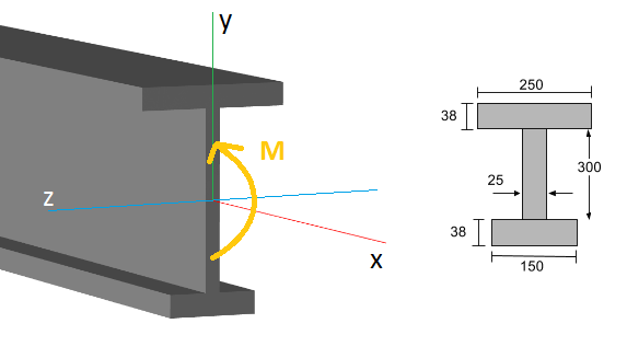
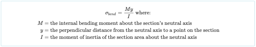
At a specific point along the beam’s length (the x-axis), there exists an internal bending moment (M), normally determined using a bending moment diagram. The general bending stress formula (or normal stress) on the section is:
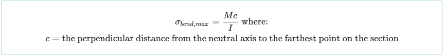
When considering a specific section of a beam, it becomes clear that the bending stress will reach its maximum value at a specific distance from the neutral axis (y). Thus, the maximum bending stress will occur either at the top or bottom of the beam section, depending on which distance is greater:
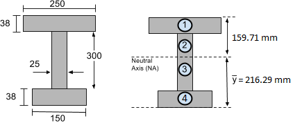
Let’s consider the real example of our I-beam shown above. In our previous moment of inertia tutorial, we already found the moment of inertia about the neutral axis to be I = 4.74×108 mm4. Additionally, in the centroid tutorial, we found the centroid and hence the location of the neutral axis to be 216.29 mm from the bottom of the section. This is shown below:
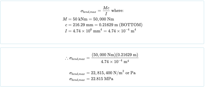
It’s usually necessary to determine the maximum bending stress experienced by a section. For instance, let’s assume we have determined, from the bending moment diagram, that the beam encounters a maximum bending moment of 50 kN-m or 50,000 Nm (after converting the bending moment units).
Then we need to find whether the top or bottom of the section is farther away from the neutral axis. Clearly, the bottom of the section has a greater distance, measuring c = 216.29 mm. With this information, we can proceed to calculate the maximum stress by employing the bending stress formula provided above:
Similarly, we could find the bending stress at the top of the section, as we know that it is y = 159.71 mm from the neutral axis (NA):

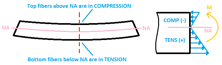
The final consideration involves determining whether the beam stress is causing compression or tension of the section’s fibers.
- If the beam sagging like a “U” shape, the top fibers experience compression (negative stress), while the bottom fibers undergo tension (positive stress).
- If the beam sags in an upside-down “U” shape, the situation is reversed: the bottom fibers are subjected to compression, while the top fibers experience tension.
2. Calculate Bending Stress using Software
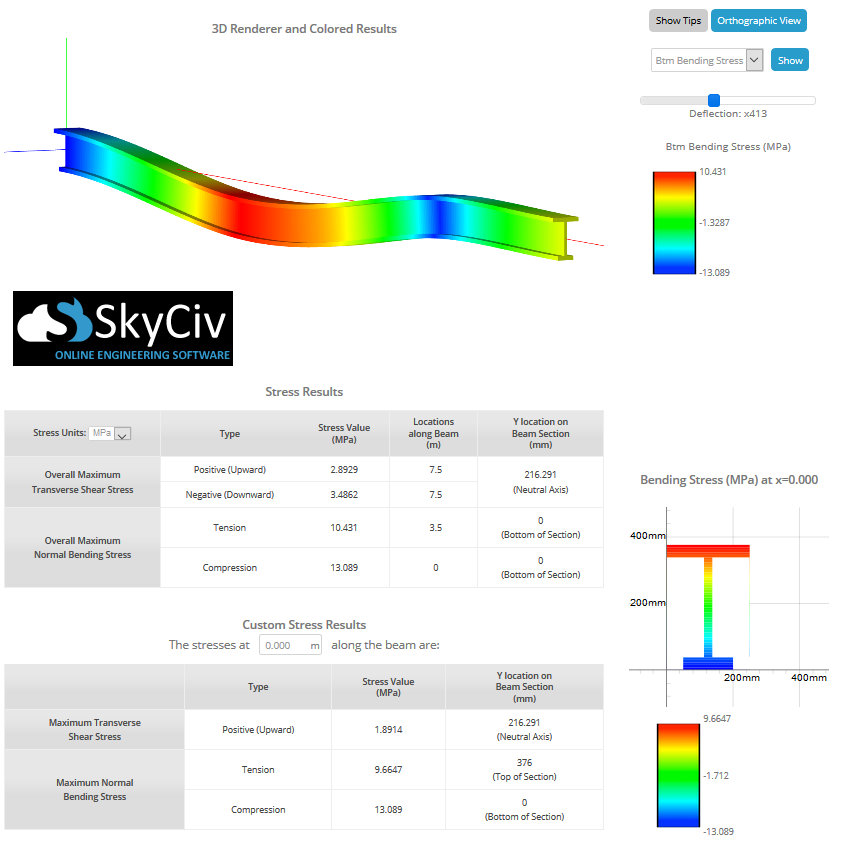
The above section has discussed bending stress formula for hand calculation, but you no longer have do it manually yourself as the SkyCiv Beam Calculator can help you find shear and bending stress in a beam in a single click. By simply modeling the beam, incorporating supports, and applying loads, you can get the max stresses using this bending stress calculator. The image below shows an example of an I-beam experiencing bending stress:
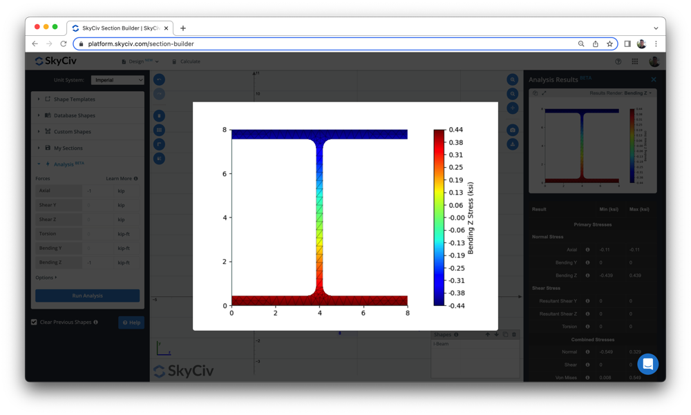
Users can also use the following Beam Stress Software to calculate the bending stress and other beam stresses, using a simple section-building tool. So check out our beam tool above or sign up to experience the software for free today!
For more beam documentations, visit our articles on calculating bending stress of a beam section, how to find bending moment, determine the reactions at the support, and beam deflection.