What is a Tributary Area and how do you calculate the Tributary Width/Area of a Member?
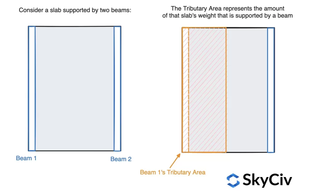
Tributary areas are a very important aspect of loading in structural analysis. The Tributary Area is the amount of area that contributes to loading a beam or column is due. You can think of it as the area that that element is responsible for carrying. It’s easily defined when looking at an example. Say you have a slab supported by two members, the tributary area would of a single beam, would be the amount of that slab it supports:
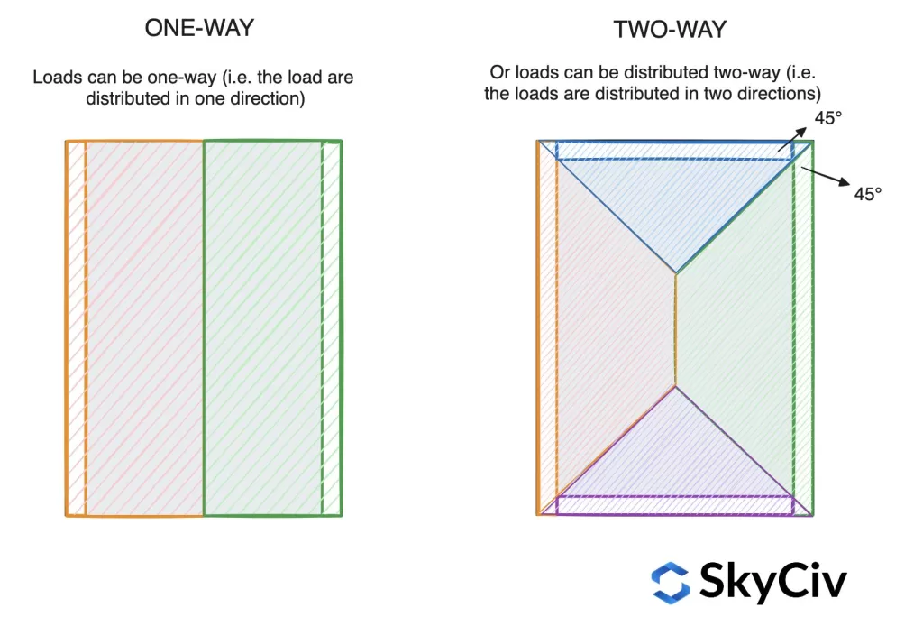
Tributary Areas can come in different shapes, depending on how the slab is being supported. For instance, a two-way support system is supported by all edges. So the load is distributed between all four members. Typically, this will result in two triangular tributary areas (by the shorter ends) and two trapezoidal areas for the longer ends. The way this is calculated is by drawing a diagonal line at 45° from each of the corners. This results in the following shape:
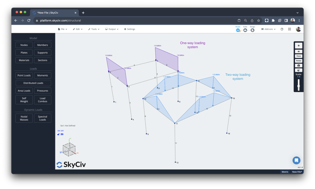
This is demonstrated by the Area Loads feature in SkyCiv, which automatically calculates the tributary area of your structure. This means as you change the shape of your structure, this is automatically calculated so your distributed loads are always in sync:
Tributary Width
The term Tributary Width is just a simplified term with a similar concept. However, rather than using area (measured in m^2 or ft^2) it is often easier to represent it by the width of the tributary area instead.
For instance, in the example below a beam might have a tributary area of 15m^2, but since it’s uniform, we can just say the member has a tributary width of 1.5m:
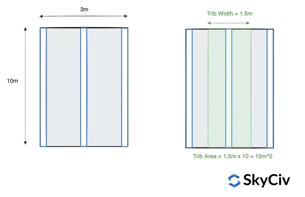
When calculating how much distributed load this results in, this becomes an easier calculation:
Slab Pressure = 15kN/m2
Beam Tributary Width = 1.5m
Distributed load = 15 * 1.5 = 22.5kN/m
As you can see, it’s just a simple multiplication to get the distributed load to be applied to the beam.
Tributary Area for Columns
Tributary areas also exist for columns, supporting slabs, below is a simplified example of how tributary areas are used in conjunction with supporting columns. The concept is more or less the same; some pressure or load is to be supported by elements, the position and direction of the element will determine how much force it is to take.
The tributary area of a column is essentially the floor area that contributes its load to that specific column. For a column supporting a uniformly distributed load, the tributary area is often depicted as a geometric shape—commonly a rectangle—defined by the spacing between adjacent columns. This area extends halfway to neighboring columns in each direction.
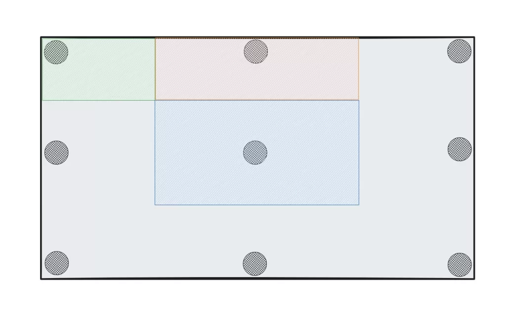
However, when dealing with irregularly distributed loads, the tributary area calculation becomes more nuanced. Sometimes circular tributary areas from the columns are extended out until they intersect with other column circular areas. This results in a complex set of tributary areas, but is another method that can be used for columns with a higher degree of accuracy.
Calculation Methods for Tributary Areas
Tributary area is determined based on the layout of the structural system and the points of support for the slab or any other load (for instance live loads, dead loads). Below are some common methods used to calculate tributary area:
- Simple Geometric Shapes:
- In many cases, the layout of the structure allows for simple geometric shapes which makes the calculation of tributary areas quite simple. For instance, a one way tributary area load calculation would be rectangular
- Polygonal Shapes:
- For more complex layouts, the tributary area can be represented by a polygon. This is common when dealing with irregularly shaped structures or unevenly distributed loads. To calculate these, you would typically draw a line at 45 degrees from each corner until those lines intersect.
- Load Path Considerations:
- The load path from the structure to its supports plays a crucial role in determining the tributary area. Consider the path along which the load is transmitted to the supporting members, and define the tributary area accordingly.
- Influence Lines:
- Influence lines are graphical tools used in structural analysis to show how a structure’s response (such as member forces or support reactions) changes as a unit load moves across the structure. They can be employed to determine the tributary area for specific members under different loading conditions.
- Finite Element Analysis (FEA):
- In more advanced structural analysis, especially for complex structures, finite element analysis (FEA) software can be employed to calculate the tributary area of a complex shape. Applying a unit load of say 1MPa and reviewing how that force is distributed to the supporting elements, is an accurate way to determine the tributary area of a structural system.
- Use of Structural Analysis Software:
- Structural analysis software, such as SkyCiv Structural 3D, often have built-in tools for calculating tributary areas. This is as simple as applying a pressure to a set of nodes and SkyCiv will automatically calculate the tributary area (and corresponding distributed loads) to be applied to the members. The software also has an in-built verification tool that will ensure all the pressure has been applied to the member correctly.