Retaining Wall Design checks as per ACI 318-19
During the process of a concrete cantilever retaining wall design, the first step is to define the preliminary dimensions and check the stability of this preliminary geometry against overturning, sliding, and bearing. Completing these stability checks involves the calculation of all the forces acting on the retaining structure. Those loads, when factored, are the input required to perform design checks on the concrete retaining wall and ensure the dimensions and provided reinforcement, will be able to withstand ultimate state loads. Using our Retaining Wall Design Software, it is possible to perform the stability checks required during the process of a concrete retaining wall design.
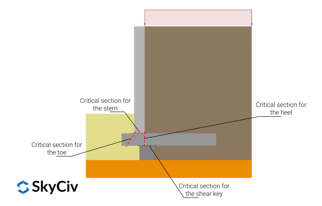
In summary, design checks on the different components of a concrete retaining wall include:
- Stem
- Critical section: Located at the base of the stem, at the face of the retaining wall base. For shear strength check, ACI 318 allows using the section at a distance d from the base as the critical one.
- Acting forces: Retained soil active pressure and additional pressure coming from surcharge loads.
- Effects to check: Flexure and shear at the critical section cantilever retaining wall’s stem.
- Heel
- Critical section: Located at the interface between the stem and the wall footing. For shear strength check, ACI 318 allows using the section at a distance d from the interface as the critical one.
- Acting forces: Retained soil weight, heel self-weight, and vertical acting surcharge. Soil pressure below the base could be included, but is usually neglected for being conservative.
- Effects to check: Shear and flexure at the critical section cantilever retaining wall’s heel.
- Toe
- Critical section: Located at the face of the stem. For shear strength check, ACI 318 allows using the section at a distance d from the face of the stem as the critical one.
- Acting forces: Bearing pressure underneath the toe. Passive soil self-weight acting above the toe is usually neglected, as it may erode or be removed.
- Effects to check: Shear and flexure at the critical section cantilever retaining wall’s toe.
- Shear key (if included)
- Critical section: Located at the interface between the shear key and the wall footing.
- Acting forces: Passive soil pressure.
- Effects to check: Shear at the critical section cantilever retaining wall’s key.
Load Factors as per ACI-318
When performing a design check on a concrete cantilever retaining wall as per the requirements of ACI-318, all the external forces that act on the structure and generate an internal force at the critical section, are factored in according to their nature, as follows:
- For lateral earth pressures, due to the soil’s weight and additional loads, the factor for calculating ultimate state loads is \(1.6\)
- For the structure’s self-weight, the factor for calculating ultimate state loads is \(1.2\)
Those factors reflect the probability of exceeding the calculated “exact” value, for the case of the structure’s self-weight, the probability of being exceeded is quite low, and therefore the factor is close to 1.0, however, external forces such as the weight and lateral pressure of the retained soil and the surcharges are more likely to take a higher value, and that’s why the load factor is closer to 2 than to 1.
Resistance reduction factors as per ACI-318
Apart from increasing the forces acting on the structure, its resistance is also reduced by applying some factors, following the LRFD (Load and Resistance Factor Design) approach. Each resistance value is reduced as follows:
- For flexure resistance, assuming the member is tension controlled, the reduction factor is \(0.9\)
- For shear resistance, the reduction factor is \(0.75\)
Design requirements as per ACI-318
Comparing the ultimate state internal forces to the reduced member resistance to that internal force, it is possible to determine whether the provided concrete section and embedded reinforcement are strong enough or not. This can be expressed in the following two equations:
- For nominal moment resistance \(M_n\) and ultimate state moment \(M_u\)
\(\phi \; M_n \geq M_u\)
- For nominal shear resistance \(V_n\) and ultimate state shear force\(V_u\)
\(\phi \; V_n \geq V_u\)
Additional requirements as per ACI-318
Apart from fulfilling the requirements mentioned above, ACI-318 presents some additional requirements for successfully completing a Concrete Retaining Wall Design:
- The reinforcement calculated for flexure on any component of the structure is checked against the beam minimum required flexural reinforcement. According to ACI-318, the beam formula is used instead of the one-way slab formula because of the lack of redundancy:
\(A_{s, \; min} = \frac{3 \sqrt{f’_c}}{f_y} b_w d\)
- Once the required steel area for flexure is calculated, the section is checked to ensure it is tension controlled, in other words making sure that the reinforcement steel yields before concrete cracks:
\(\varepsilon_t = \frac{\varepsilon_c}{c}(d-c) > 0.005\)
Where \(c = \frac{a}{\beta_1}\), \(a = 1.31 A_s\), \(\varepsilon_c = 0.003\) (assuming concrete cracks at that strain level), and \(d\) is the distance from the compression edge to the center of the reinforcement in tension.
- Some minimum transverse reinforcement area is calculated for each component of the Cantilever Concrete Retaining Wall, using the ratios given in Table 11.6.1 of ACI-318
- Development and splice lengths are also calculated for each component of the Cantilever Concrete Retaining Wall, using the criteria given in 25.4.2 of ACI-318
SkyCiv Retaining Wall Calculator
SkyCiv offers a free Retaining Wall Calculator that will check sliding in retaining wall and perform a stability analysis on your retaining walls. The paid version also displays the full calculations, so you can see step by step, how to calculate the stability of a retaining wall against overturning, sliding and bearing! With the paid account, it is also possible to perform design checks as per ACI on the retaining wall.

Product Developer
BEng (Civil)