In this tutorial, we will walk you step-by-step through designing a connection in SkyCiv Structural 3D.
First of all, the design UI comes with five (5) main tabs namely:
- Project
- Assembly
- Fixtures
- Loads
- Analysis
Project
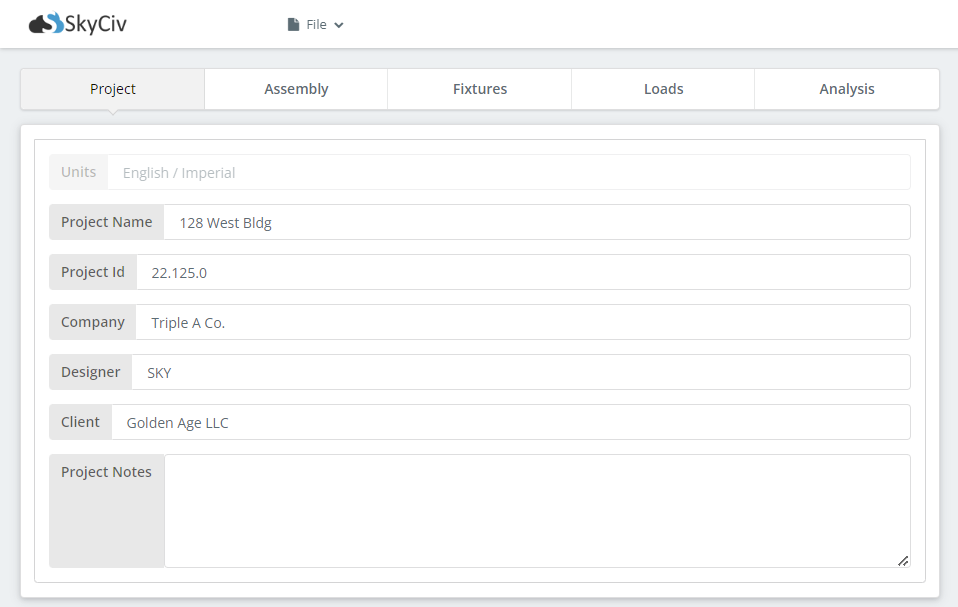
The Project tab is where you provide all your project information. Although not required to perform the calculations, project information such as the following are beneficial to identity and classify all of your designs.
- Project Name
- Project ID
- Company
- Designer
- Client
- Project Notes
Assembly
The second tab is where you build your connection assembly.
Column
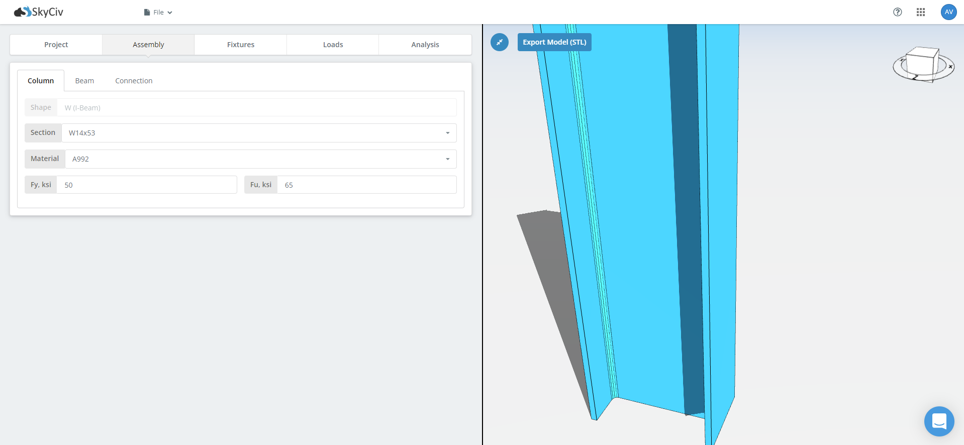
We start with the support member which is usually a column. Select your section size in the drop-down selection after the Section label. After that, select your material grade. The most common material grades are provided in the drop-down menu. In case you want a custom grade, simply modify the Fy and Fu fields. Take note of the units indicated for each field.
Beam
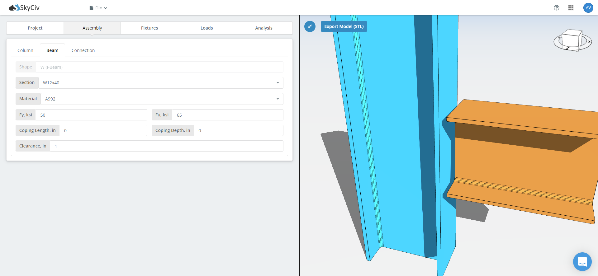
Next to the column tab is the beam tab. Similarly, supply the needed information for your beam member such as its section size and material grade. There will also be options to add cope dimensions and beam clearance. Add these dimensions if deemed necessary.
Connection
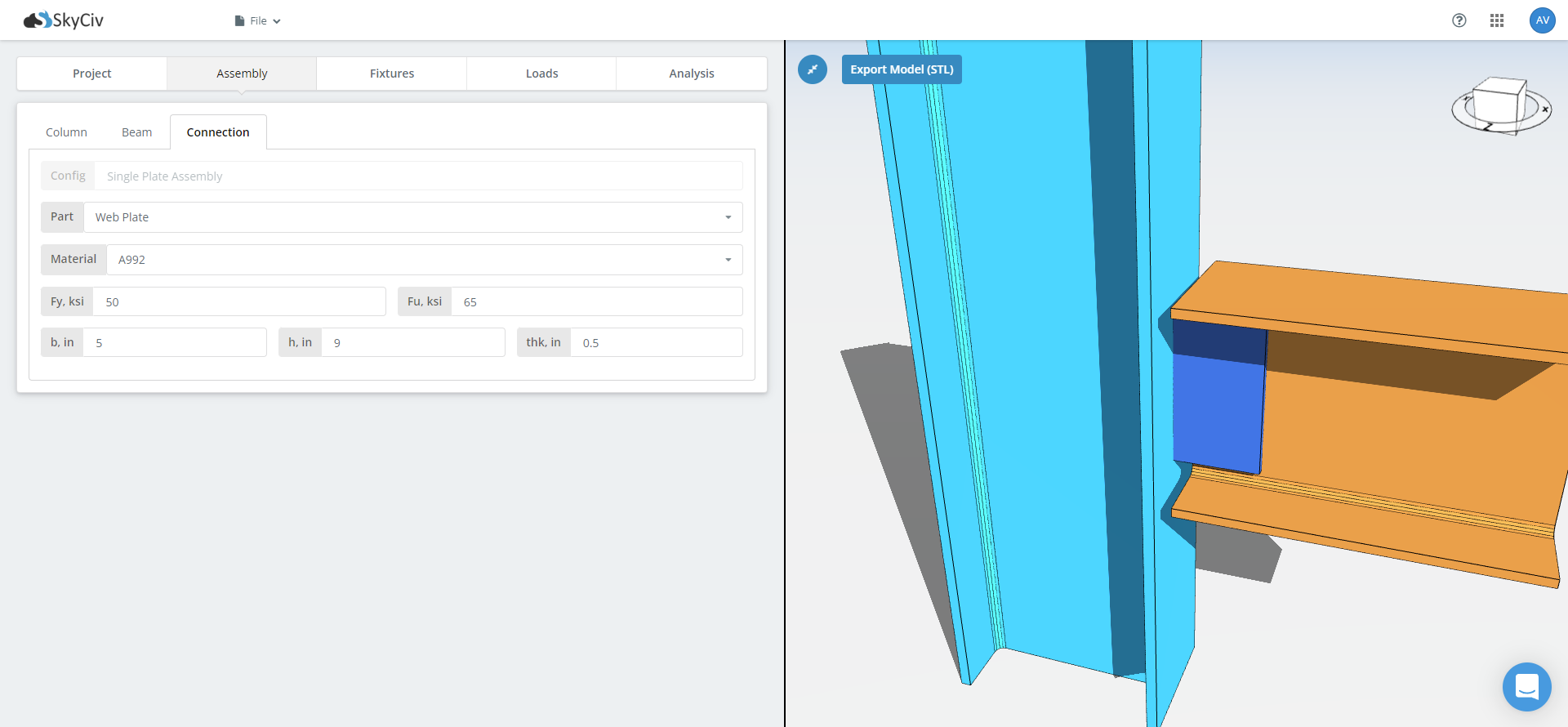
Finally, the assembly won’t be complete without your connecting materials. In this tab, you will fill out all the necessary details such as material grades, thicknesses, widths, lengths, among others. Make sure you do not forget to switch between flange connection and web connection, if available, when filling out this tab.
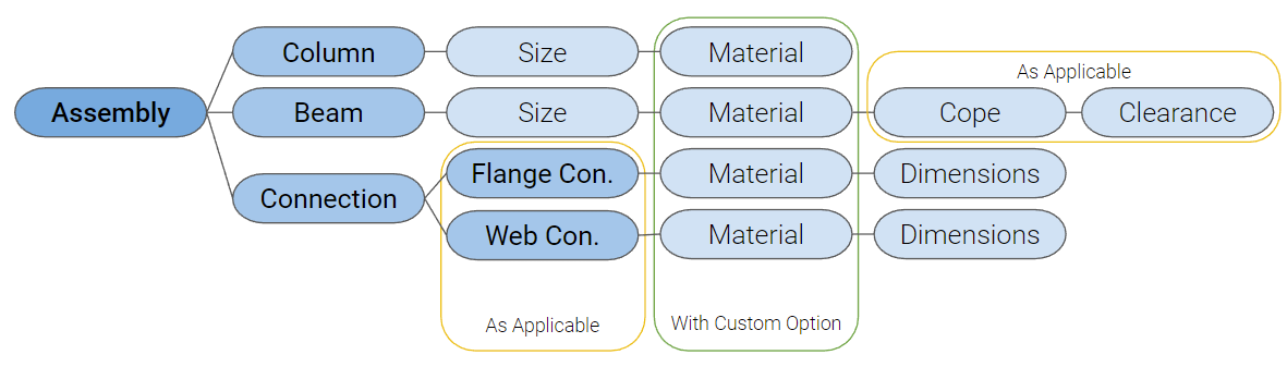
Once all necessary fields are filled for each tab, the model will automatically render the 3D figure. Feel free to check out this cool feature in the free connection calculator even without an account!
Fixtures
Under the main Fixture tab are all the other sub-group of fixtures labeled numerically. A short description of each fixture is also indicated right below the tab name.
To start designing each fixture, select first which type of fixture you are going to use. There are only two types available—the bolted and the welded type. In some of the connections, the fixture type will be pre-selected and locked. If your desired type is currently not available, you may send a feature request to SkyCiv’s support team.
Bolt
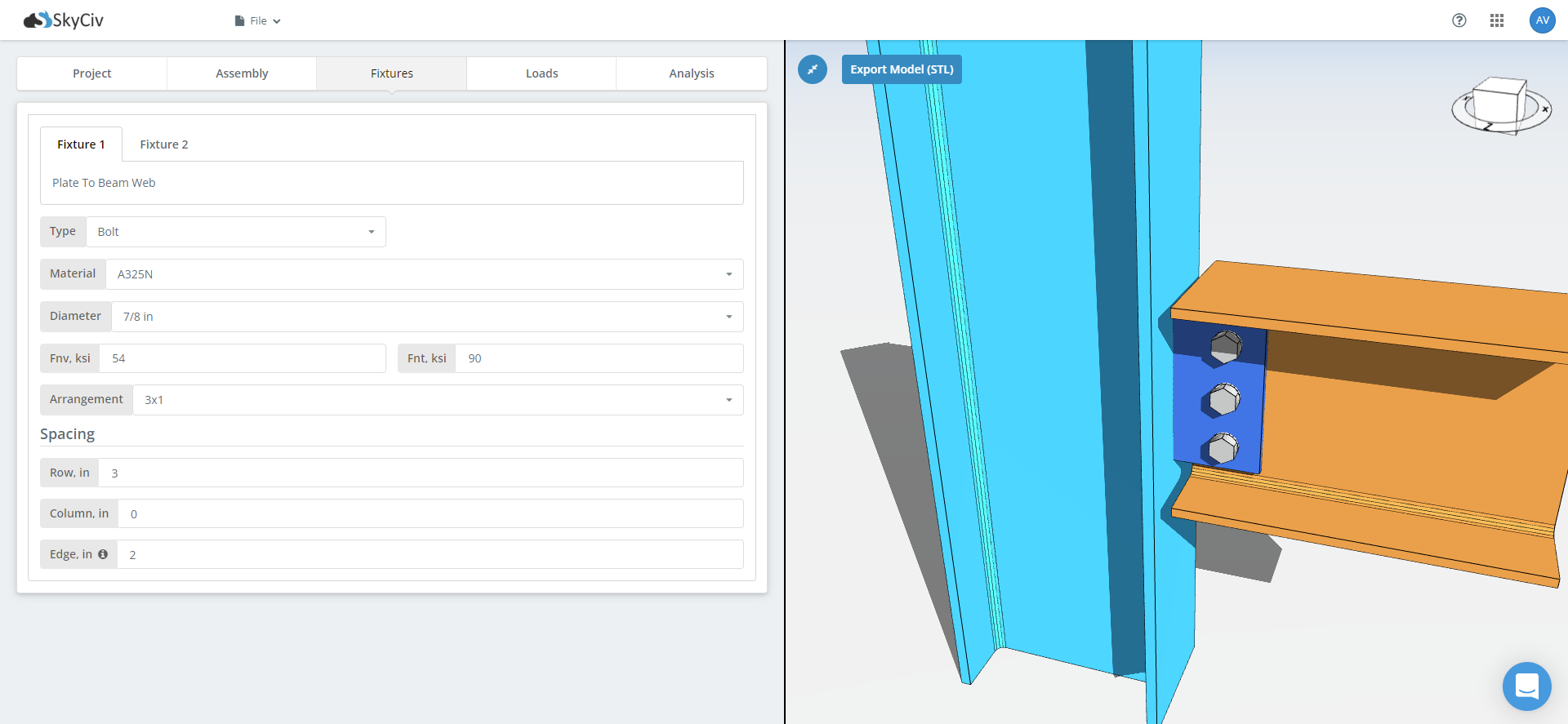
If a bolted connection type is chosen, you will be presented with the needed information regarding the bolt to be used such as:
- Material
- Diameter
- Bolt Shear and Tensile Strength
- Arrangement
- Row Spacing
- Column Spacing
- Edge Distance
For the ease of users, most of these fields are made with a drop-down list. There is also a tool-tip on the Edge distance information to guide the users on what this information pertains to.
In addition, once all the required fields have been filled out, the model will automatically render the bolts in the connection. In case you want to make changes in your design, like trying out another bolt size, or increasing your bolt spacings, you can automatically see the changes in your connection through our real-time rendering.
SkyCiv Connection Design software will help you advance your spatial recognition and boost your imagination.
Weld

Building your weld information is not as intricate as the bolted connection. Here, you will just need to key in the following information.
- Material
- Weld Strength
- Size
The 3D model will automatically update once you finish setting up your weld fixture.
Loads

Adding your loads in the loads table is a straightforward process. Just write inside the available cells the design load you’re considering and you’re good to go.
At this point, you can ignore the Load Types in the last column as this is not that practical for steel connection design. In this specialized practice, it is conventional to use the factored as the design load.
Don’t miss out on the full features of the SkyCiv Connection Design software. You can always sign-up for a free 14 day trial anytime, anywhere. No installation, no set-up required.
Analysis
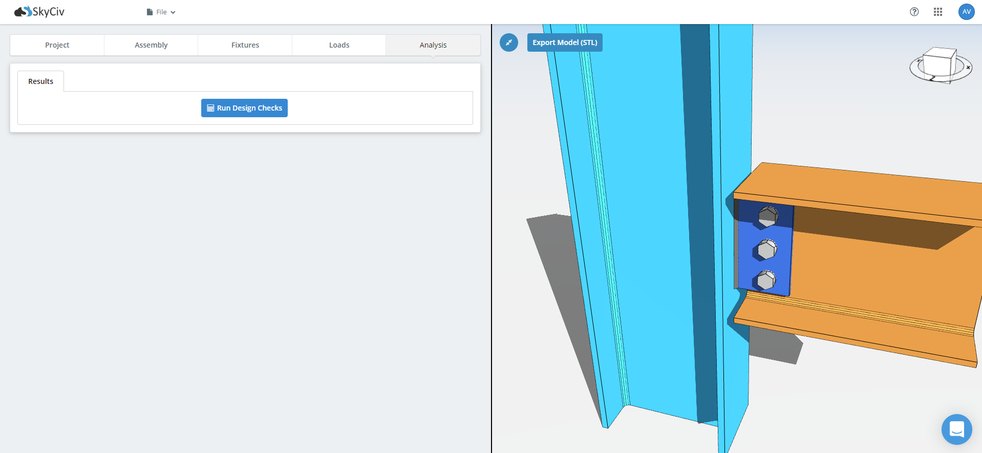
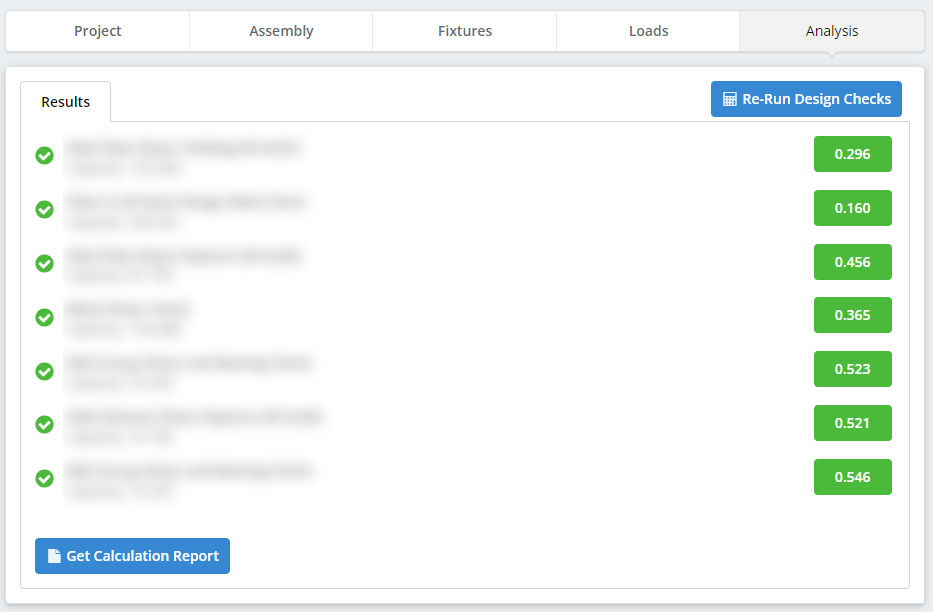
Finally, after every required information regarding your connection is provided, you can now run the structural analysis. With SkyCiv Connection Design software’s powerful computing ability, you can see the tabulated and graphical results in seconds.
Once satisfied with the results, you can now generate the detailed calculation report by clicking on the Get Calculation Report button. You can also have the option to save the report locally by clicking the Download PDF or Download HTML options.
Start Today
Eager to get your hands dirty? Start designing using our Free Connection Design Calculator. Power structural analysis software, right within your browser.
SkyCiv Connection Design
Make the most of SkyCiv Structural Steel Connection Design by signing up for Free 14-Day Trial!
Connection Design Standalone
Want to use the connection design module only? Click the button below for the standalone pricing!