In this article, we will show you how to design a reinforced concrete beam using SkyCiv software. This tutorial covers two software options provided by SkyCiv for beam design: The SkyCiv Beam and Structural 3D. We will delve into both tools to help you access and design beams effectively. At the end of the article, we will also apply the method of coefficients prescribed by ACI-318-19 for RC beam design.
If you are new to beam design, we would recommend reading some introductory SkyCiv articles:
- What is reinforced concrete?
- How to calculate the bending moment resistance for a beam section?
- How to analyze a continuous beam?
These tutorials will help you gain a better understanding of the general process of designing beams.
If you are new at SkyCiv, Sign up and test the software yourself!
SkyCiv Beam Software
The first stop is creating the beam model in the SkyCiv Beam Software. We indicate the steps required: (In parenthesis, we show the example data):
- On the dashboard page, select the beam module.
- Create a beam defining its length (66 ft).
- Go to supports and define hinges or simple rods (hinge at the beginning and the end; rod at third points).
- Go to sections and create a rectangular one (rectangular section; width=18 in; height=24 in).
- Then select the distributed load button and assign one, two, or more as you need for (superimposed dead load = 0.25 kip/ft; live load = 0.40 kip/ft)
- The next step is create some load combinations (\({L_d = 1.2\times D + 1.6\times L}\))
- Finally, solve the beam!
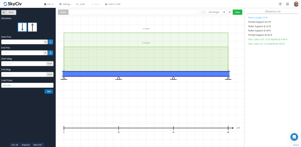
Figure 1: Beam model with dead and live loads applied
After solving the beam, we can check the results, like the bending diagram, to get their maximum values along the element length. The following images show the final output.
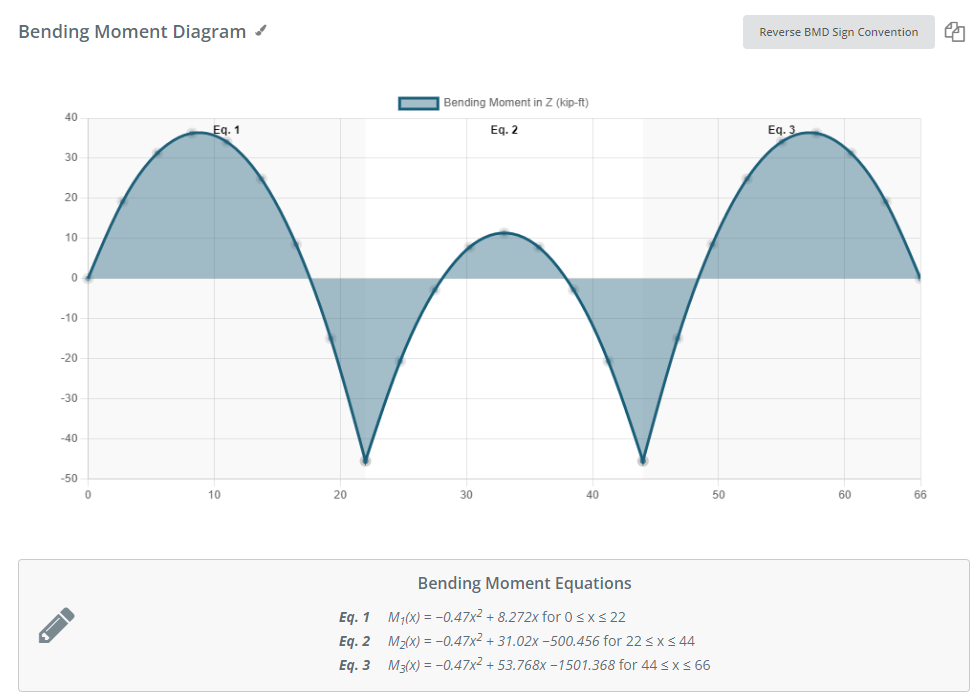
Figure 2: Bending moment diagram due to the specified load combination
The SkyCiv Beam Software gives us a table with the maximum values for forces, stresses, and displacement:
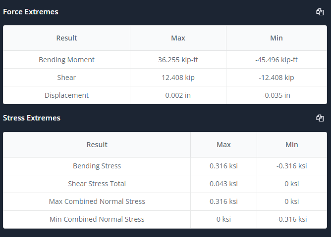
Figure 3: Summary table
Now is the time to select the design tab and select and define the input as reinforcement layout, analysis sections, some coefficients, load combinations, etc. Look at figures 4 and 5 for more description.
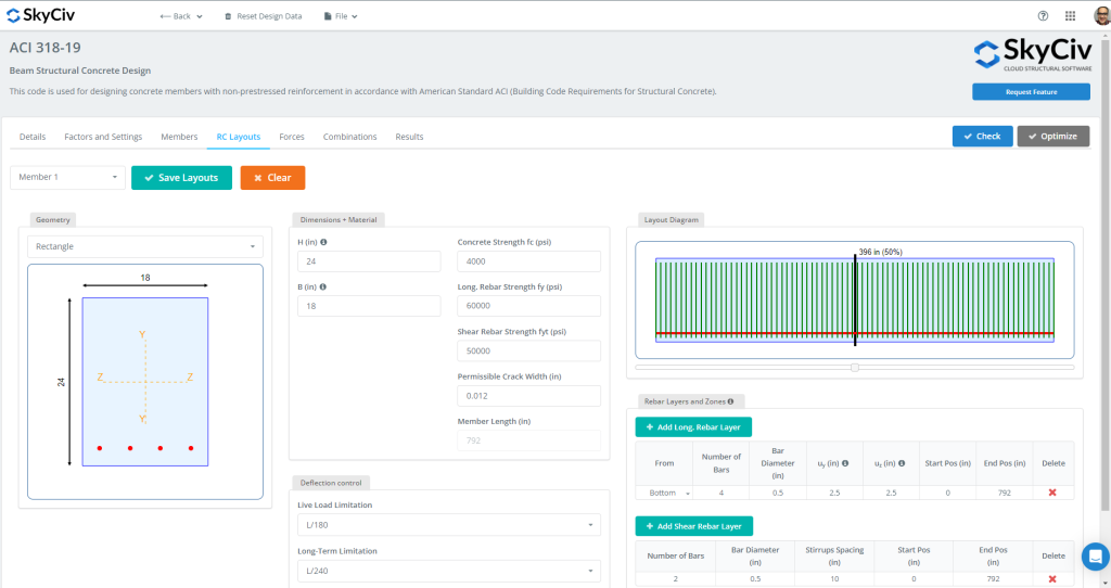
Figure 4: RC beam layouts
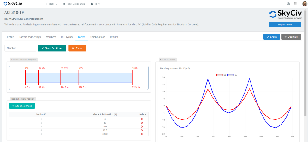
Figure 5: Forces and sections to evaluate when designing
Once all the data is ready, we can click the “Check” button. This action will give us then the results and the capacity ratios for strength and serviceability.
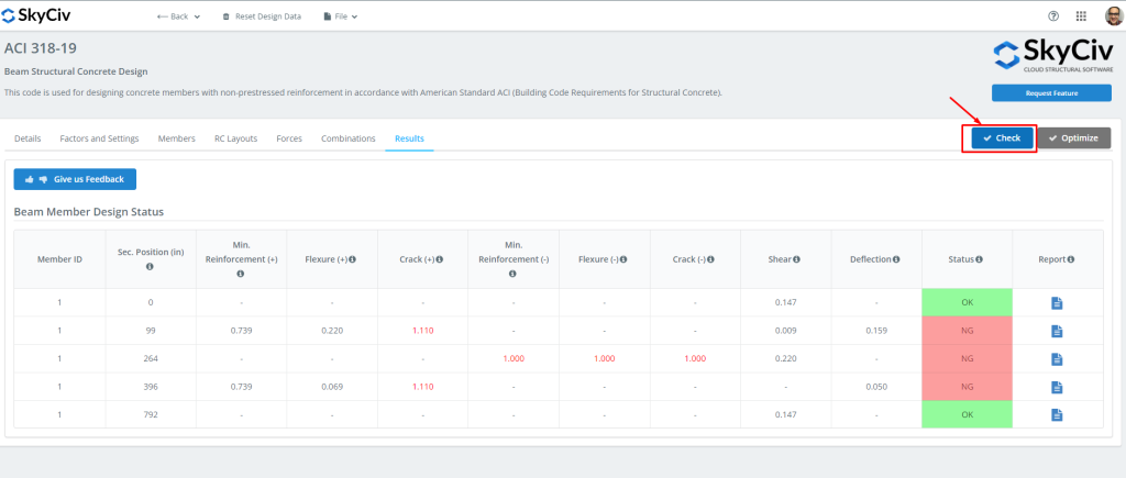
Figure 6: Beam Module Design Results.
You can then download all the reports you need for!
If you are new at SkyCiv, Sign up and test the software yourself!
SkyCiv Structural 3D
Now is the time to use Structural 3D! We recommend just returning to the beam software and clicking on the “Open in S3D” button. This will help us prepare the model and its inputs in S3D.
Once we clicked the change button, the model was automatically created. Remember to save it! (If you need to familiarize yourself with this module, look at this tutorial link!)
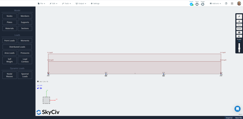
Figure 7: Automatically created model in S3D.
Now go directly to the “Solve” icon choosing the “Linear analysis” option. Feel free to check and compare results; we will use the “Design” option. It is time to define all the characteristics required to evaluate the beam on the different tabs.
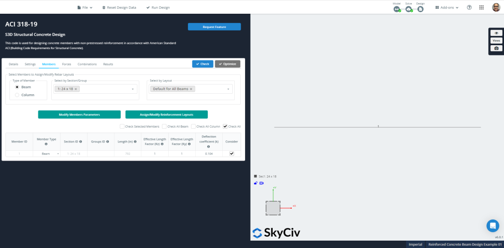
Figure 8: Members’ information for design
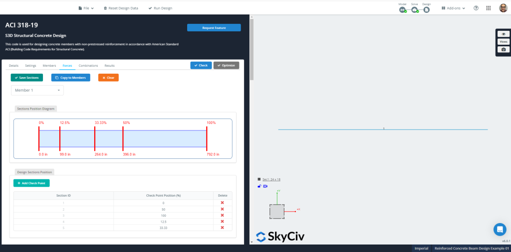
Figure 9: Members’ forces and sections for design
SkyCiv can check for a particular defined RC layout or calculate a section reinforcement optimization. We’d like to suggest you run this latter option.
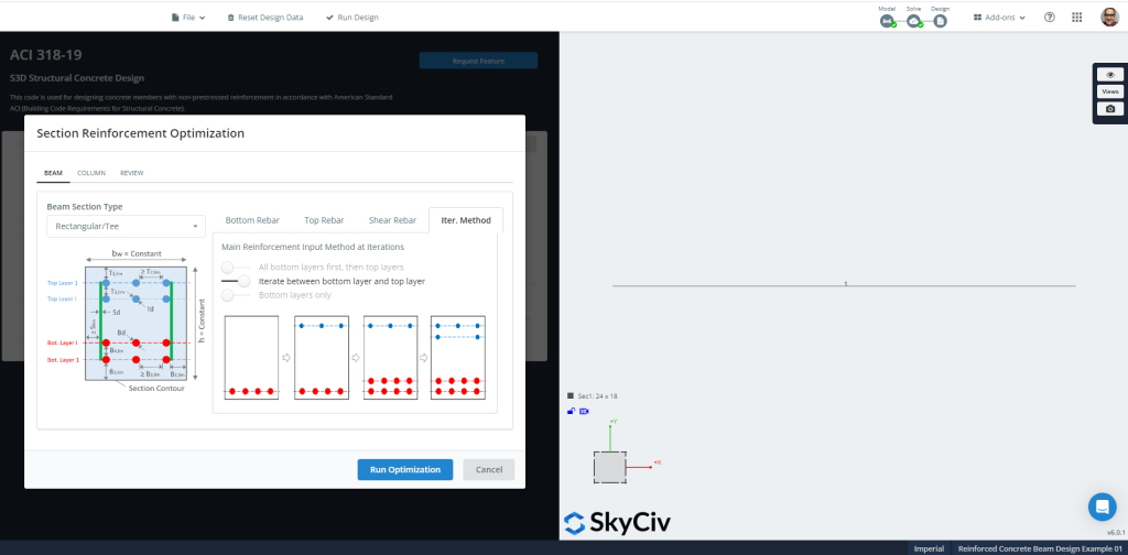
Figure 10: Section Reinforcement Optimization.
Figures 11 and 12 show the final result and the suggested section reinforcement calculated for the optimization design.
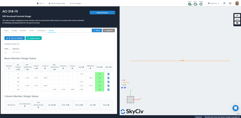
Figure 11: Structural Concrete Design Results
You can then download all the reports you need for!
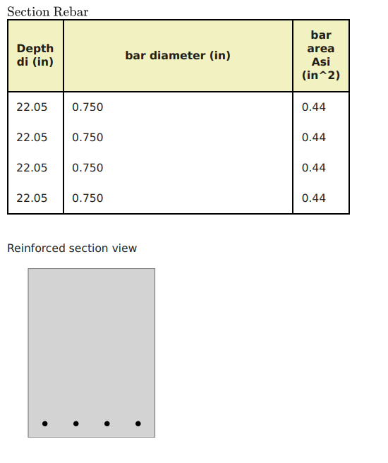
Figure 12: Optimization in Section Reinforcement Steel
If you are new at SkyCiv, Sign up and test the software yourself!
ACI-318 Approximate Equations
When designing a continuous beam, ACI-318 permits using moment coefficients for bending calculations. (For more examples, feel free to visit these SkyCiv’s articles about Slab Design)
Moments at critical sections are calculated with: \( M_u = coefficient \times w_u \times l_n^2 \). Where the coefficient can be obtained from the following:
- Exterior span:
- Negative exterior: \(\frac{1}{16}\)
- Positive midspan: \(\frac{1}{14}\)
- Negative interior:\(\frac{1}{10}\)
- Interior span:
- Negative: \(\frac{1}{11}\)
- Positive midspan: \(\frac{1}{16}\)
We’ll select two cases: the absolute maximum value for positive and negative bending moments.
\(wu=1.2\times D + 1.6\times L = 1.2 \times 0.25 + 1.6 \times 0.4 = 0.94 \frac{kip}{ft} \)
\(M_{u,neg} = {\frac{1}{10}}{\times 0.94 {\frac{kip}{ft}}}{\times {(22 ft)}^2} = 45.50 {kip}{ft} \)
\(M_{u,pos} = {\frac{1}{14}}{\times 0.94 {\frac{kip}{ft}}}{\times {(22 ft)}^2} = 32.50 {kip}{ft} \)
Flexure resistance calculation for negative moment, \({M_{u,neg} = 45.50 {kip}{ft}}\)
- Assumed tension-controlled section. \({\phi_f = 0.9}\)
- Beam width, \({b=18 in}\)
- Steel reinforcement area, \({A_s = \frac{M_u}{\phi_f\times 0.9d\times fy}= \frac{45.50 kip-ft \times 12 in -ft }{0.9\times 0.9(17 in )\times 60 ksi}=0.66 {in}^2}\)
- \({\rho_{min} = 0.003162}\). Steel minimum reinforcement area, \({A_{s,min}=\rho_{min}\times b\times d = 0.003162 \times 18 in \times 17 in =0.968 {in}^2}\). Now, check if the section is behaving as tension-controlled.
- \({a = \frac{A_s\times f_y}{0.85\times f’c\times b} = \frac{0.968 {in}^2\times 60 ksi}{0.85\times 4 ksi\times 18 in }= 0.95 in}\)
- \({c = \frac{a}{\beta_1}=\frac{0.95 in}{0.85} = 1.12 in }\)
- \({\varepsilon_t = (\frac{0.003}{c})\times {(d – c)} = (\frac{0.003}{1.12 in})\times {(17in – 1.12 in)} = 0.0425 > 0.005 }\) Ok!, it’s a tension-controlled section!.
Flexure resistance calculation for positive moment, \({M_{u,pos} = 32.50 {kip}{ft}}\)
- Assumed tension-controlled section. \({\phi_f = 0.9}\)
- Beam width, \({b=18 in}\)
- Steel reinforcement area, \({A_s = \frac{M_u}{\phi_f\times 0.9d\times fy}= \frac{32.50 kip-ft \times 12 in -ft }{0.9\times 0.9(17 in )\times 60 ksi}=0.472 {in}^2}\)
- \({\rho_{min} = 0.003162}\). Steel minimum reinforcement area, \({A_{s,min}=\rho_{min}\times b\times d = 0.003162 \times 18 in \times 17 in =0.968 {in}^2}\). Now, check if the section is behaving as tension-controlled.
- \({a = \frac{A_s\times f_y}{0.85\times f’c\times b} = \frac{0.968 {in}^2\times 60 ksi}{0.85\times 4 ksi\times 18 in }= 0.95 in}\)
- \({c = \frac{a}{\beta_1}=\frac{0.95 in}{0.85} = 1.12 in }\)
- \({\varepsilon_t = (\frac{0.003}{c})\times {(d – c)} = (\frac{0.003}{1.12 in})\times {(17in – 1.12 in)} = 0.0425 > 0.005 }\) Ok!, it’s a tension-controlled section!.
Finally, we can see that for both moments, negative and positive, the result is to assign a minimum flexural reinforcement. The steel rebar area required equals \(0.968 {in}^2\).
Related Tutorials
If you are new at SkyCiv, Sign up and test the software yourself!