Area loads are used primarily in conjuncture with members, which is useful when applied correctly. They take pressures and generate equivalent distributed loads (DLs) that are applied to members. These equivalent distributed loads are what is used for the member analysis. Area loads are useful when not wanting to model the plate, which may introduce unwanted stiffness into the model. Like with other loads, you can assign a load group and subsequent load case to area loads.
Types of Area Loads
- One-Way:
- Loads are distributed using one-way action
- All non-rectangular convex polygons are now supported.
- Continuous and intersecting members are now supported
- Member offsets are now considered (having member offsets could lead to variance issues)
- Can detect or exclude internal members (including angled members)
- Supports stepped loads (variable loads)
- Cantilevered loads are no longer supported because they caused issues and violated basic statics in most instances.
- Two-Way:
- Loads are distributed using two-way action
- Requires 3 or 4 nodes to identify extents of area load
- Orthogonal internal members are auto-detected
- Load area must be rectangular or triangular
- Continuous members are NOT supported
- Member offsets are NOT considered (having member offsets could lead to variance issues)
- Loads do NOT auto-update
- Column Wind Loads:
- Requires 3 or 4 nodes to identify extents of area load
- Can step pressure values along the length of column/member
- Multiple elevations and pressure changes supported
- Loads members that follow a single column direction
- Open Structure:
- Requires 3 or 4 nodes to identify extents of area load
- Distributes loads to members based on the tributary area of the member itself
- Apply to members in global X, Y, Z planes, or all members
- Non-Rectangular:
- Load area can be any 2D shape.
- Requires 3 or more members to identify extents of area load.
- All ends of the members in the list must be attached to another member in the list.
- Member offsets are NOT considered (having member offsets could lead to variance issues)
- Continuous members are supported
- One-Way: (Legacy)
- Loads are distributed using one-way action
- Requires 3 or 4 nodes to identify extents of area load
- Span direction of internal members must be identified
- Load area must be rectangular or triangular
- Continuous members are NOT supported
- Member offsets are NOT considered (having member offsets could lead to variance issues)
- Variance Checks Explained
The following examples will go through each type of area load and their differences.
Area Loads vs. Equivalent Distributed Loads
When area loads are created and applied to an area, they will originally show up as a cube shape, indicating a constant pressure. What is actually used in the analysis is the equivalent distributed loads that are applied to members. Depending on the type of area load, these distributed loads will depend on various factors but will mostly depend on the tributary width/spacing of the members located within the area load. These equivalent distributed loads can be toggled on and off in the viewing space.
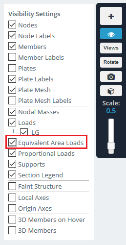
To toggle on and off the equivalent distributed loads, go to the Visibility Settings on the right-hand side (looks like an eye) and click on Equivalent Area Loads:
The results for a simple square frame can be shown below:

Note: It is always good practice to check the equivalent distributed loads to verify the area loads you are applying are distributing and loading the members correctly.
Note: Normal Distributed Loads and equivalent distributed loads are distinguished by their red and green colors, respectively.
Example: One-Way Area Load (New)
Corner Node IDs: Identifies the extents of the area load – must be 3 or 4 nodes (use the toggle button to switch directions of the direction to apply the load)
Pressure Magnitude: Load magnitude that is going to be applied
Load Direction: Can be Global X, Y, Z, or the planes’ Local Axis
Excluded Member IDs: Exclude members by their ID
Exclude internal Members: you can filter internal members to control what internal members are applied to [Off, Angled Members, All Internal Members]
Step Intervals: [Optional] enter in comma separated magnitudes and distances to apply a variable load across a member (including internal members)
Load Group: Load group as identified in the Load Group and Load Cases documentation
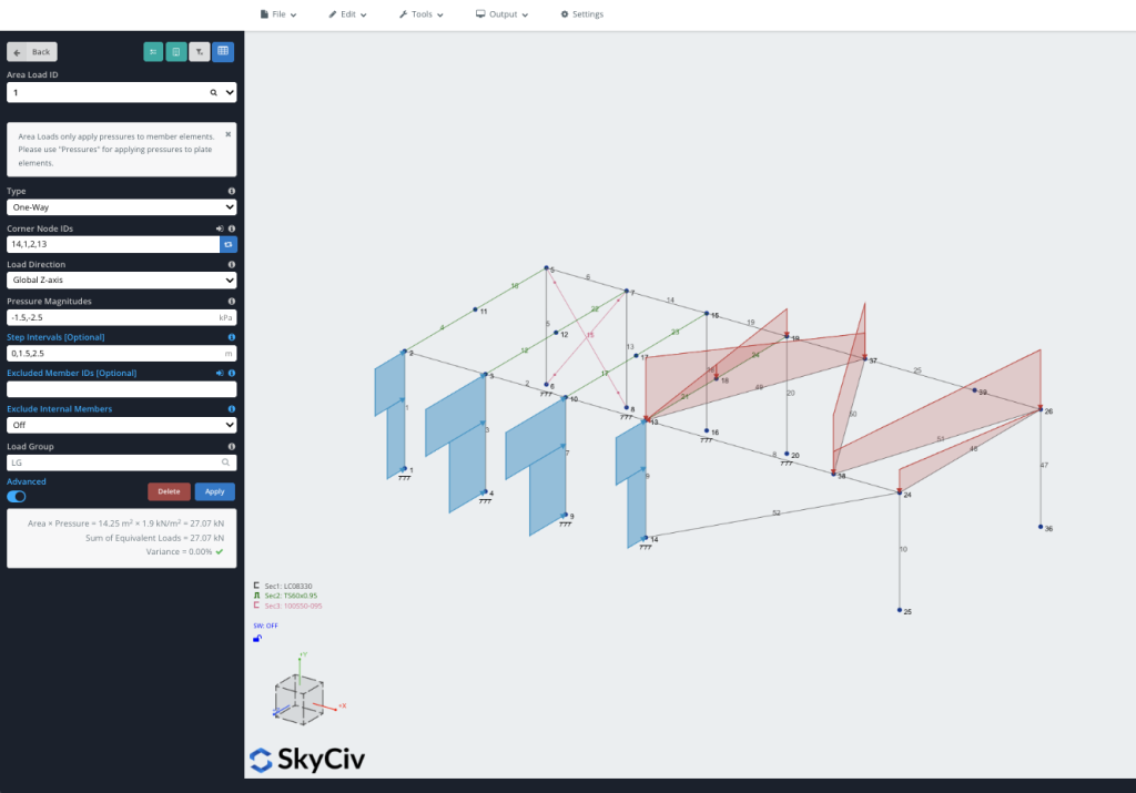
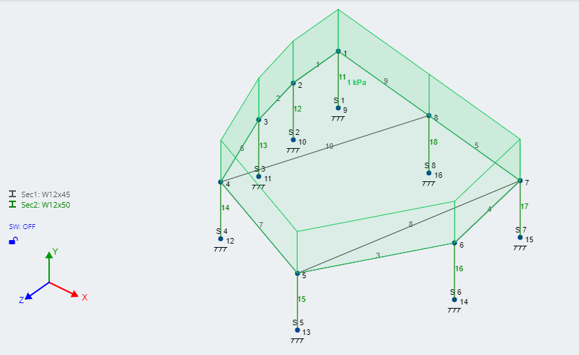
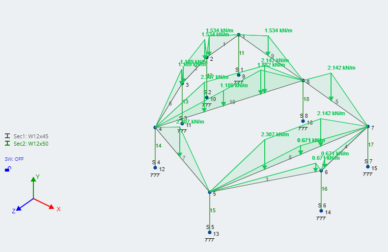
In this example, we’ll consider two are loads (one Wind Load and one Dead Load) and apply different settings to show the functionality available with this option. The blue load in the model below shows the options, using the Step Intervals option which lets user comma seperate a magnitude and distance pair. Here we are going from -1.5MPa from 0m to 1.5m to -2.5MPa from 1.5m to 2.5m. We can see this reflected in the distributed loads applied to the members:
This option also has functionality to exclude this functionality or exclude certain types of internal members. On top of switching the direction, users have control over what type of internal members to include:
Example: Two Way Area Load
Two-Way loads require a much larger number of computations to be completed by the solver compared to One-Way loads, which is why we highly recommend using One-Way Loads whenever possible.
Note: Two-Way loading will only support orthogonal framing within the extents of the area load. Angled framing will not work respond properly to Two-Way Area Loads.
Note: Two-Way Area Loads will only distribute correctly if all interior members are split, meaning: unlike in the One-Way case, “girders” contained in your area load must be split at each point where another member frames into it. This can be accomplished very easily by selecting all of those members at once and using the “Split Members” function.
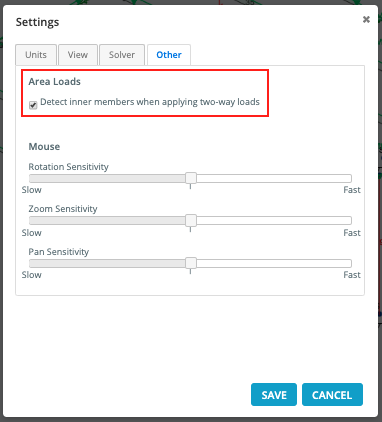
Because of the impact on the calculation time, you will need to confirm in the Settings > Other that you would like Two-Way loads to distribute to interior members as shown:
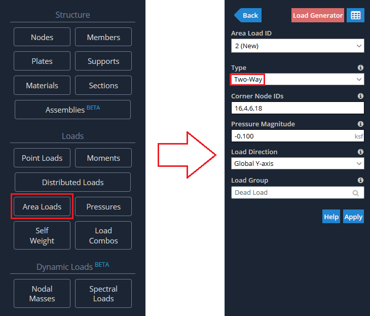
The input fields required to apply a Two-Way Area Load are:
Corner Node IDs: Identifies the extents of the area load – must be 3 or 4 nodes
Pressure Magnitude: Load magnitude that is going to be applied
Load Direction: Can be Global X, Y, Z, or the planes’ Local Axis
Load Group: Load group as identified in the Load Group and Load Cases documentation
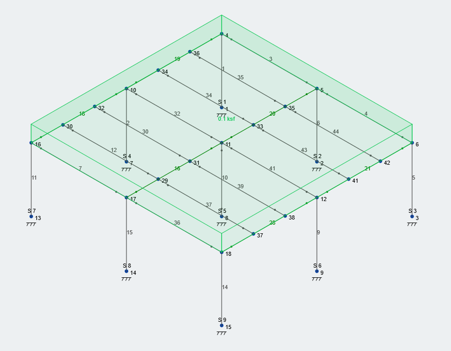
We will use the same structure as in the One-Way example for consistency. We will assume that the Two-Way area load is a “Dead Load” with the same extents, direction, and magnitude as in the previous case:
The resultant area load will look the same as the previous case when looking at the pressure.
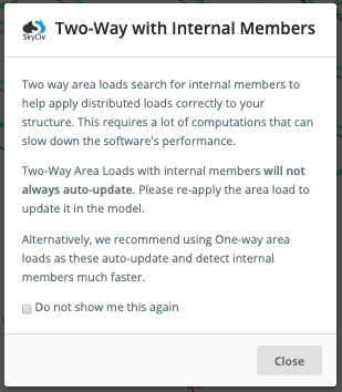
Make sure that all members inside the area load are split and do not have nodes along their length. When first applying a Two-Way load, you will be greeted with this message from Structural 3D:
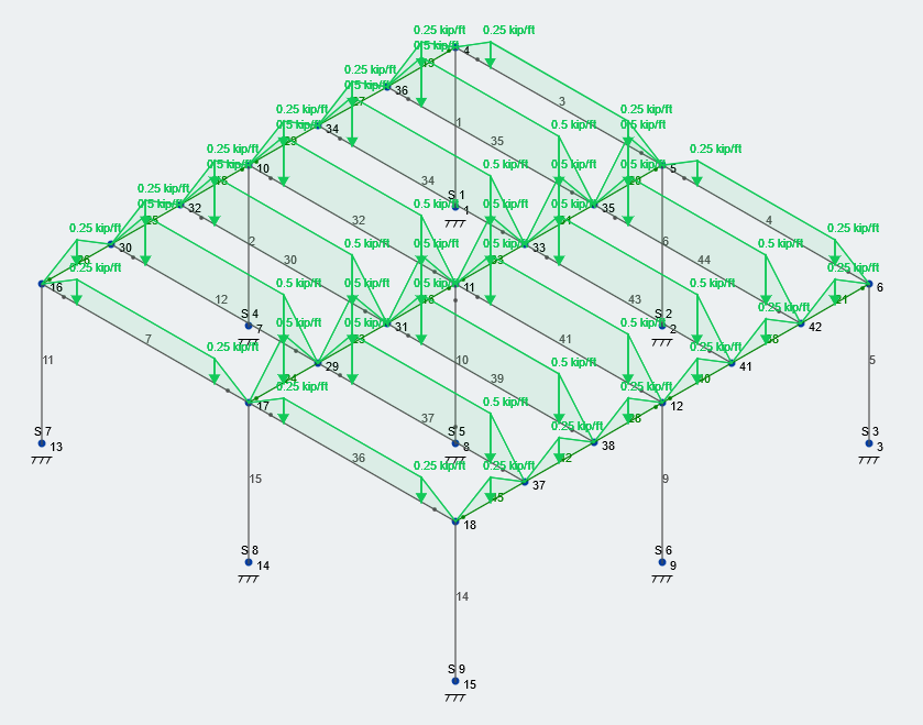
Toggle on the equivalent distributed loads to see the differences between One-Way and Two-Way Loads:
Member showing a variance of > 0%
SkyCiv has an inbuilt variance check for both one-way and two-way area loads, to ensure the loads are being built correctly. If you’re struggling to get this to show a variance of 0% (meaning the area load force is applied to the members correctly) you can try this help video.
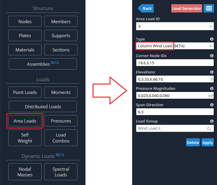
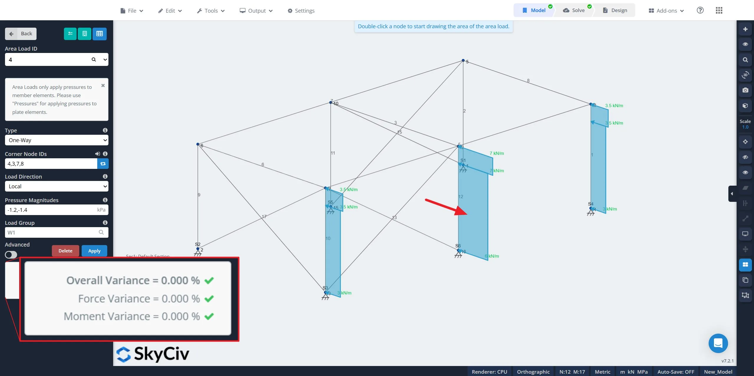
Example: Column Wind Load
The inputs required for application of Column Wind Loads are:
Corner Nodes: Identifies the extents of the area load – must be 3 or 4 nodes
Elevations: Comma separated Elevations (Global Y-Axis) for wind loads. These are the elevation ranges that match up to the Pressure Magnitudes below.
Pressure Magnitudes: Comma separated Pressure Magnitudes for wind loads. These will be applied based on the above Elevations.
Span Direction: Similar to One-Way Loads: the span direction of the columns. The direction is indicated by the vector between two nodes
We will use the same structure as in the One-Way example for consistency. The height of the one-story structure is 10 ft. We will assume our structure is closed, and apply Column Wind Loads to the “front” side of our structure; or the Global minus-X direction. We will assume from wind load calculations – You can get your wind load calculations directly from the SkyCiv Wind Load Software – that we have a lateral wind pressure of 20 psf from 0-3.33 ft, 40 psf from 3.33 to 6.66 ft, and 60 ft from 6.66 ft to the top of the structure. We also need to make sure that the column direction is correct, so we will the direction from Node 3 to Node 6 (Global Y-axis). If we input all of this information correctly, we should see this input window:
Note: The order of nodes in the ‘Span Direction’ field will indicate the “zero elevation” and “end elevation”
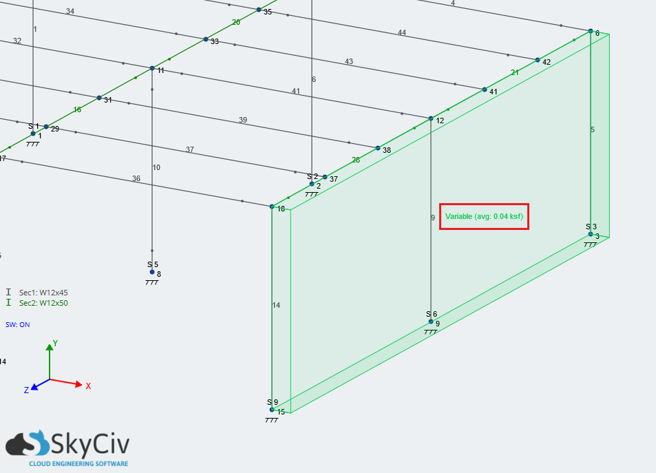
Then subsequently, with the equivalent distributed loads off, it will display a constant pressure as the average of all pressure on the structure:
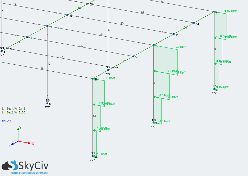
Turn on the equivalent distributed loads to see the expected steps in loading and distribution among the columns:
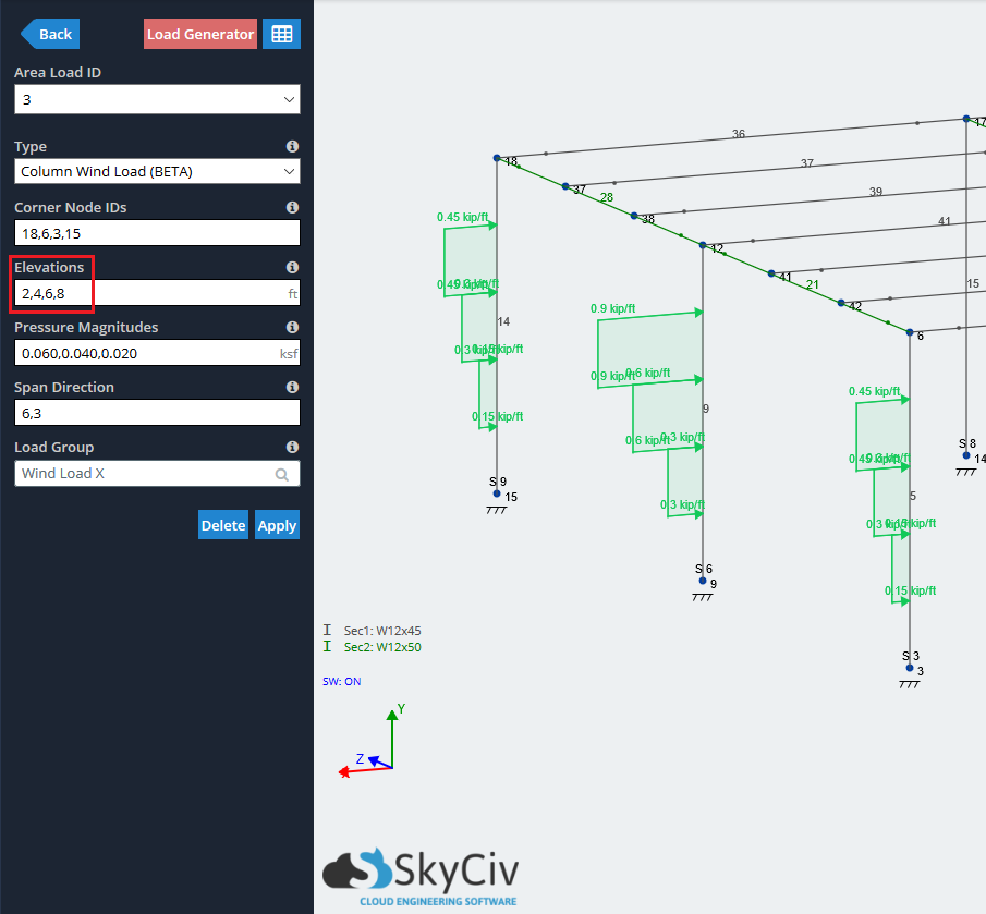
A note about Column Wind Loads:
There are other similar functions you can use the Column Wind Load function for:
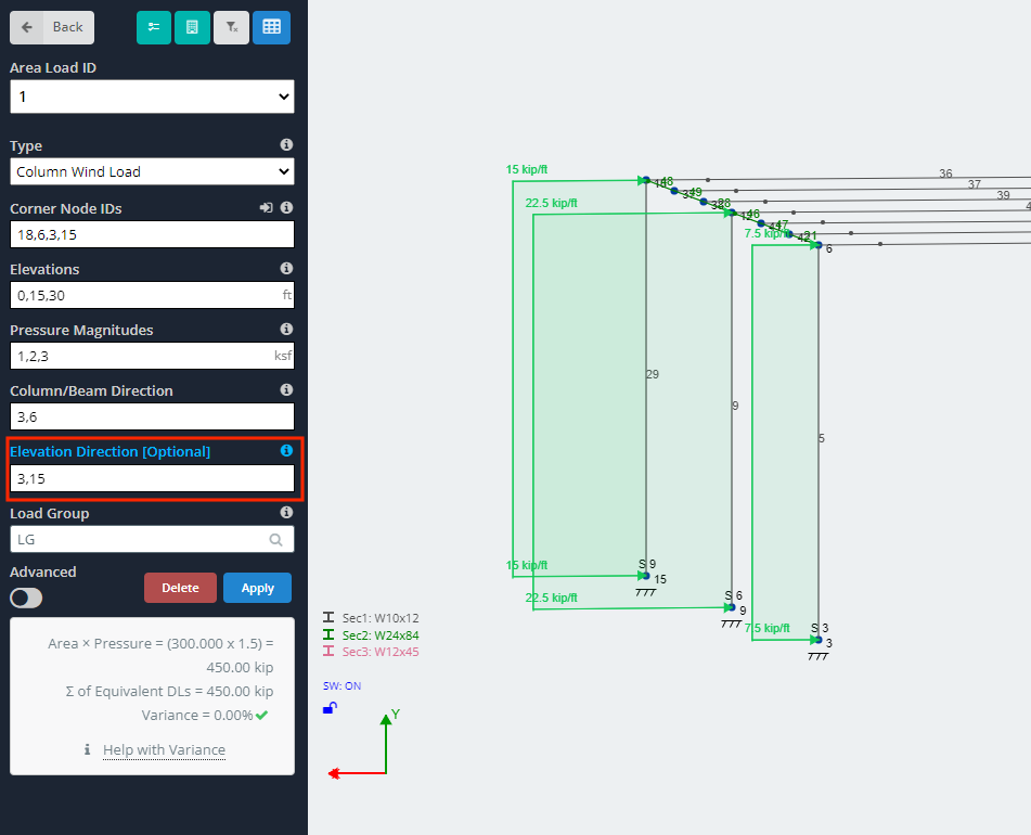
- You can offset the load from the column ends. The first number in the “Elevations” field must be greater than the Y-coordinate of the bottom node of the columns, and vice versa for the top.

- You can specify the direction of the elevations with the optional “Elevation Direction” input. This takes in two nodes to form a direction and length vector. This means that values in the elevation input and corresponding pressure magnitude input will only be considered if they reside along the length of this vector. Note that the Global Y-Axis is used if no input to “Elevation Direction” is provided.

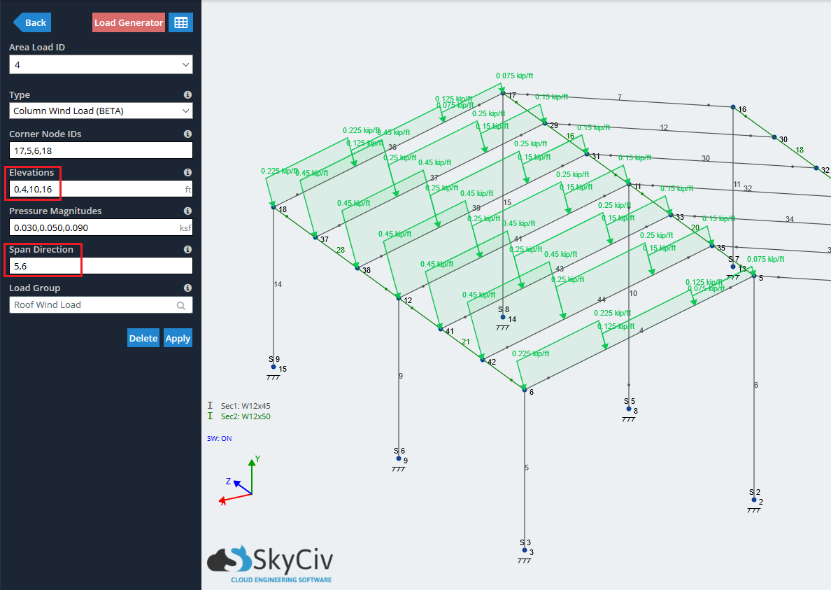
- You can also apply a Column Wind Load to a slanted plane (shown using the Local axis direction). In this case, the “Elevation” corresponds to the location along the length of the sloped roof member. Using the same structure, but with the middle ridge raised 4 feet:

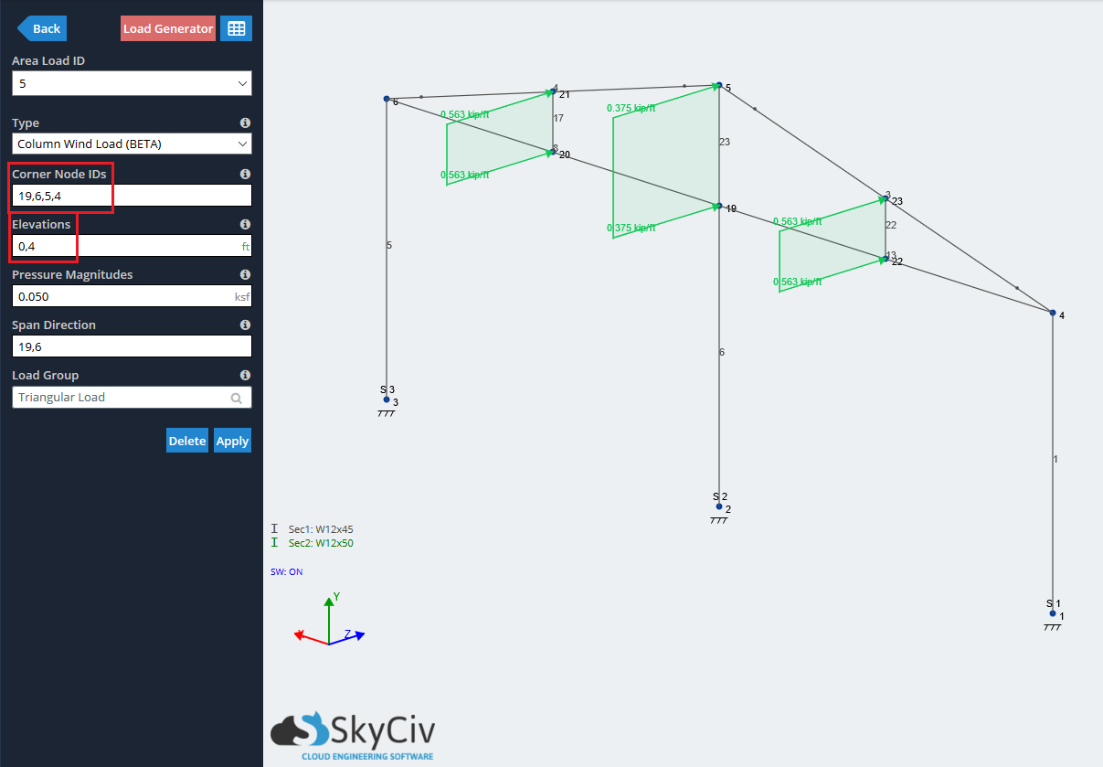
- Lastly, you can use a triangular shape as the bounded extents of a Column Wind Load. Using the same structure, but with the bottom-chords connecting the triangle (rest of structure hidden for clarity)

Example: Open Structure
The last method of applying Area Loads is the Open Structure Area Load. Like it sounds Open Structure Area Loads are meant to be applied to open structures or those which have their members subject directly to outside elements. with this method, Structural 3D will calculate the equivalent distributed loads based on the tributary width of the section, which depends on its orientation to the load. As the exposed area of the section gets wider, the equivalent distributed load increases for the same constant Open Structure Area Load. Similar to the Column Wind Load method, this will most commonly be used in conjuncture with wind loads. You can get your wind load calculations directly from the SkyCiv Wind Design Software
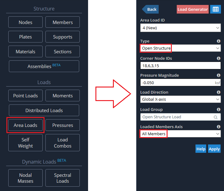
The input fields required to apply an Open Structure Area Load are:
Corner Node IDs: Identifies the extents of the area load – must be 3 or 4 nodes
Pressure Magnitude: Load magnitude that is going to be applied
Load Direction: Can be Global X, Y, Z, or the planes’ Local Axis
Load Group: Load group as identified in the Load Group and Load Cases documentation
Loaded Members Axis: Apply the loads to just members in the X, Y, Z axis, or all members
Similar to before, we will use the same structure as shown in the previous modules except for this time, we will assume there are two bays of “X-braces” on the front face of the structure. The main difference between the Open Structure and Column Wind Loads is that the latter can vary the pressure, while Open Structure loads cannot. Let’s assume there is a constant lateral wind pressure towards the “X-braces” of 50 psf. For Loaded Members Axis, we want to load ALL members, including the braces, which are not in any orthogonal axis. If we input all the relevant values, we should see this input window:
By default, the area load will be represented by a pressure load and magnitude as shown below:
Toggle on the equivalent distributed loads to see how the loads are being distributed:
As noted previously, we selected the option “All Members” for the Loaded Members Axis selection. If you wanted to load just members following the orthogonal axis, you would select “X, Y, Z Members” and see this result:
Note: Open Structure Area Loads can be applied in any Global Axis direction, or in the Local Axis of the plane bounded by the Corner Node IDs
Example: Non-Rectangular
Non-rectangular area loads require more computation to be accurately interpreted by the solver compared to One-Way loads or Two-Way loads, which is why we highly recommend using non-rectangular loads only on non-rectangular member configurations.
Non-rectangular loads are similar to Two-Way loads as the action assumes the load is supported by all members in the system. As the closest support may be a beam OR girder, the span direction does not need to be identified.
Note: Non-rectangular loads will still correctly be applied if members are not split. However, the time required to apply a load and solve will be reduced if the members are split. If possible, It’s recommended to split members before applying a non-rectangular area load.
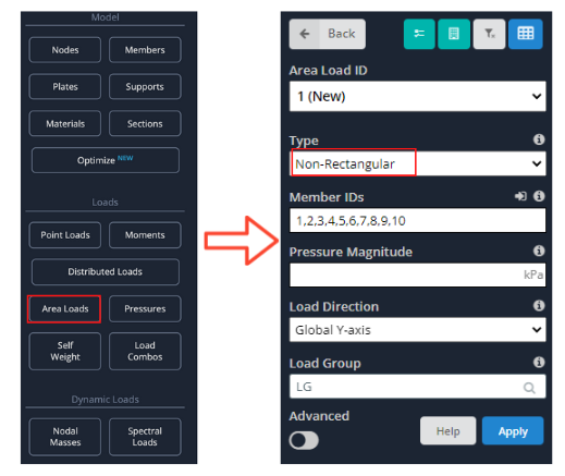
The input fields required to apply an Open Structure Area Load are:
Member IDs: Identifies the supports of the load and in turn the members the load will be applied to – must be 3 or more members
Pressure Magnitude: Load magnitude that is going to be applied
Load Direction: Can be Global X, Y, Z, or the planes’ Local Axis
Load Group: Load group as identified in the Load Group and Load Cases documentation
Loaded Members Axis: Apply the loads to just members in the X, Y, Z axis, or all members
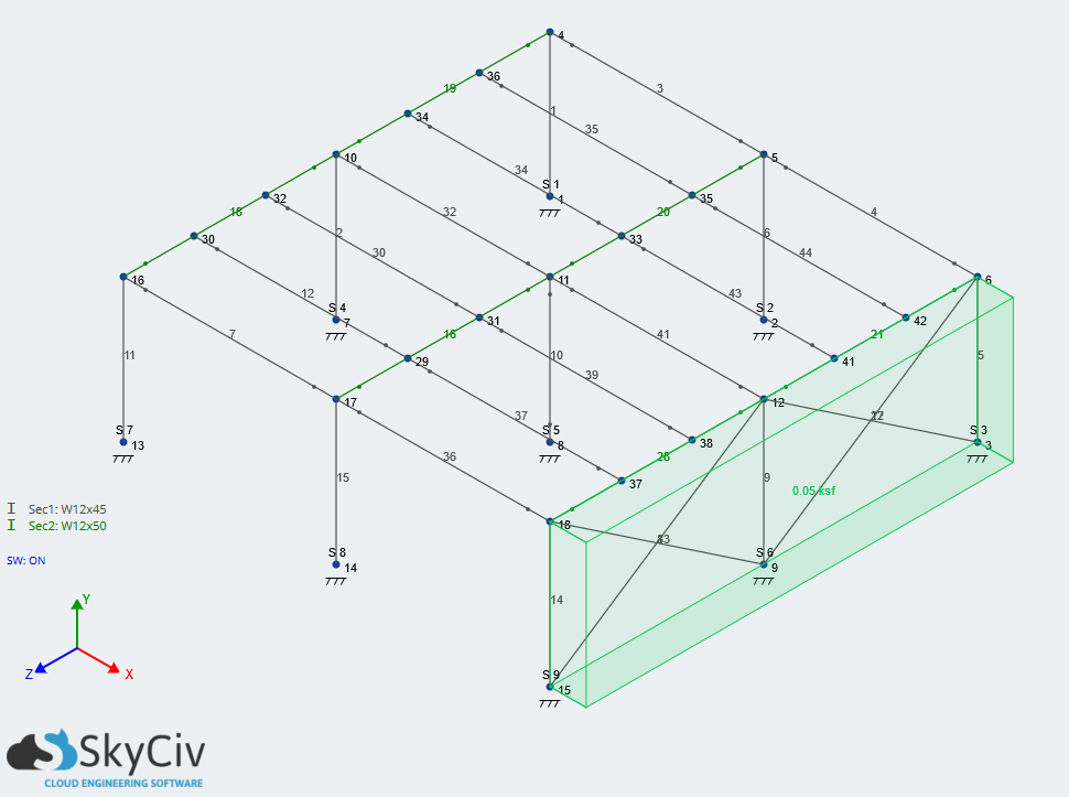
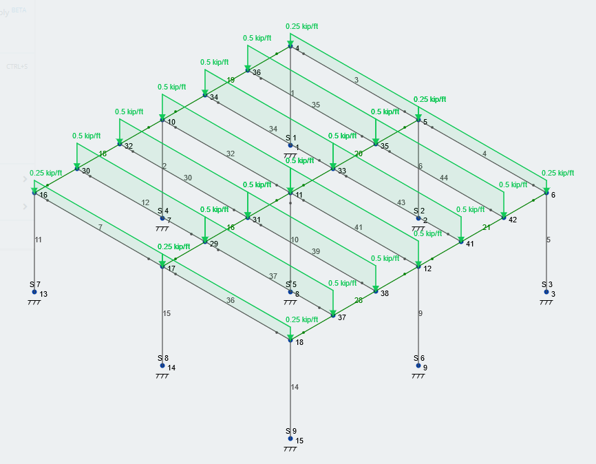
As non-rectangular area loads should be applied to structures with non-rectangular member configurations, we will be using a different structure than the ones seen in the previous examples. We will assume the load will be applied to all members normal to the global Y-axis.
By default, the area load will be represented by a pressure load and magnitude as shown below:
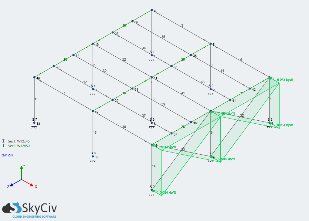
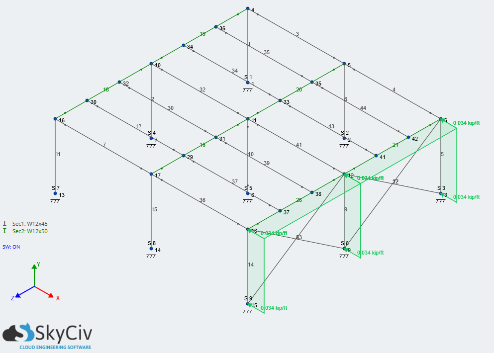
Toggle on the equivalent distributed loads to see how the loads are being distributed:
Why do the forces look irregular?
The area load is broken into a number of distributed loads, based on the three allowable shapes (triangular, rectangular and trapezoidal) to apply the most accurate forces to your members. Multiple distributed loads are added to a single member, which will cause some overlap force and the resulting forces to look irregular. Additionally, members that span two tributary areas may have two entirely different distributed loads. For instance, consider member 10 above, since the two tributary areas it supports are different in size, there will be two different shaped distributed loads. This is normal behaviour, despite the forces looking irregular.
Example: One-Way Area Load (Legacy)
The input fields required to apply a One-Way Area Load are:
Corner Node IDs: Identifies the extents of the area load – must be 3 or 4 nodes
Pressure Magnitude: Load magnitude that is going to be applied
Load Direction: Can be Global X, Y, Z, or the planes’ Local Axis
Span Direction: Direction of interior members; span direction of members that will experience the load
Load Group: Load group as identified in the Load Group and Load Cases documentation
For this example, we’ll be looking at how one-way area loads can be applied to a one-story warehouse-type structure with beams framing into girders. The beams are spaced at 5 feet on-center. Instead of modeling a slab with a plate and affecting the stiffness of our structure, we will use one-way area loads. Let’s assume that the floor load is a Live Load, and it 100 psf. One-way area loads are meant to be used when framing is orthogonal to each other, as shown in our example structure:
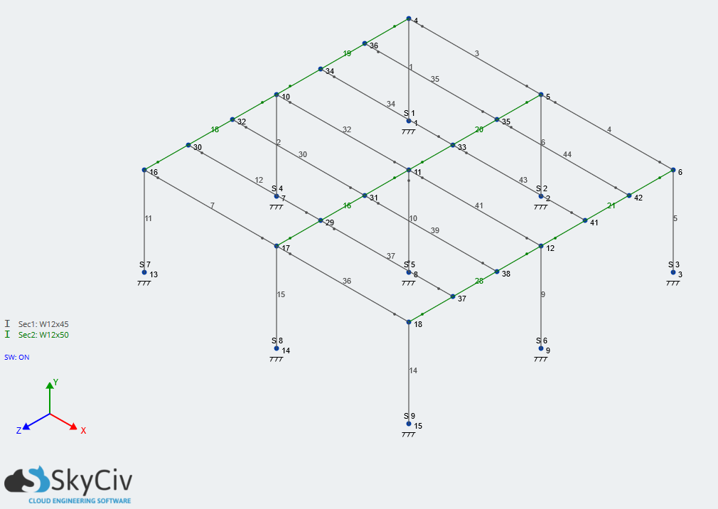
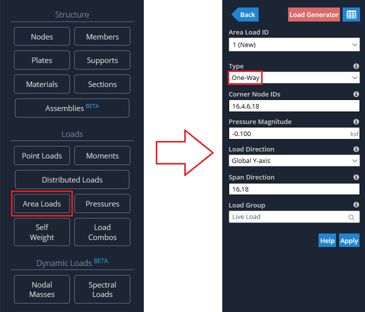
To apply a One-Way Area Load, click the Area Loads, button to open the menu. Select “‘One-Way” from the Type dropdown. Put in the corner nodes of the floor to identify the extent of the area load. The pressure is 100 psf, so input -0.100 ksf. We input a negative pressure because it will be acting along the Global Y-axis, but in the downward direction. Change the span direction to go from Node 16 to Node 18, the direction of our internal members (beams). Type in “Live Load” for the load group, as you would for other loads.
Note: The order of the corner nodes must follow the clockwise or counterclockwise direction.

Variance Checks
SkyCiv has some built-in variance checks to ensure the total area load force is correctly applied to your model. This helps users identify issues in the application of Area Loads to Distributed or Point Loads. To review the variance checks for a single area load, simply click the area load you wish to investigate:
This will calculate the applied loads and compare them to the sum of distributed loads to ensure all of it is captured and applied correctly as distributed or point loads. If you have a lot of area loads, you can review them all at once by clicking Tools – Check Area Load Variance, which will show a summary of the area loads:
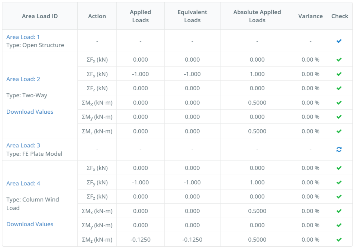
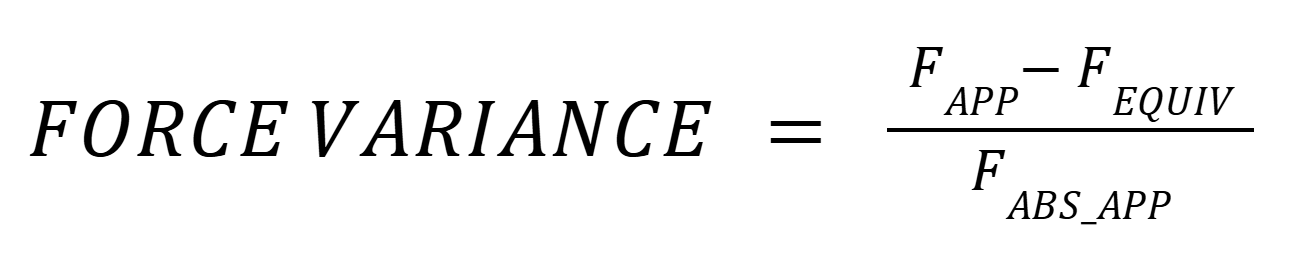
If an area load has intervals, it will first be divided into distinct sub-polygons. Each individual sub-polygon (or the area load itself if there are no intervals) is then checked for forces in the 3 principal global axis (FX, FY, FZ), as well as for moments about the 3 principal global axis (MX, MY, MZ). The formulas used to compute the force variance is the following:
Where:
- Applied Force (FAPP): For each sub-polygon, the applied force is equal to the product of area and magnitude. When an area load has multiple sub-polygons (i.e. when intervals are used), FAPP is equal to the sum of all of the sub-polygon’s applied forces.
- Equivalent Force (FEQUIV): An equivalent force is calculated for each equivalent distributed load generated by the area load functions. FEQUIV is equal to the sum of all of the equivalent forces (either computed from distributed loads or generated directly as point loads).
- Absolute Applied Force (FABS_APP): Similar to FAPP, with the exception that we take the absolute value of each applied force to get the total applied force, regardless of the direction of application.
The formulas used to compute the moment variance is the following:
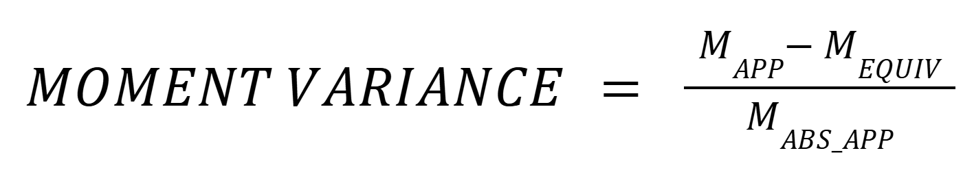
Where:
- Applied Moment (MAPP): For each sub-polygon, the applied moment is equal to the product of FAPP and the lever arm from FAPP to the center of gravity of the area load. When an area load has multiple sub-polygons (i.e. when intervals are used), MAPP is equal to the sum of all of the sub-polygon’s applied moments.
- Equivalent Moment (MEQUIV): An equivalent moment is calculated for each equivalent distributed load (or point load) generated by the area load functions. It is equal to the product of FEQUIV and the lever arm between FEQUIV and the center of gravity of the area load. MEQUIV is equal to the sum of all of the equivalent moments.
- Absolute Applied Moment (MABS_APP): To compute each sub-polygon’s absolute applied moment, we use the sub-polygon’s absolute applied force and we place it on the node that creates the maximum moment for each direction. We then take the lever arm from the area load’s center of gravity to that point and keep the absolute value of the result.
All of the intermediate calculations are available for review in .json format by pressing the “Download values” button in the variance table.
My Variance is not 0%, what can I do?
If your variance is off, it means the pressure is not applied correctly. Try the following steps to fix this:
- Split Members: Try splitting the members surrounding the boundary nodes. Area loads needs a closed space to function correctly, continuous members that span outside of these nodes can cause issues.
- Column Wind Loads: Make sure the last elevation value equals the distance of the bounding box. This will ensure the correct Pressure x Area value is calculated.
- Tolerance issues: Ensure nodes are all perfectly aligned. Area loads includes some leniency for tolerance, but these are limited to ensure the accuracy of the software. Please check your node coordinates to ensure they align correctly.