Steel, Wood and Cold rolled design standards – fully integrated with analysis software
SkyCiv has built in member design modules for both SkyCiv Structural 3D and SkyCiv Beam. These models are fully integrated – which means you model them in the program and all the results, properties and dimensions are loaded directly into the program, so that you don’t have to spend the time re-entering all of this information.
Learn how to design a steel connection using SkyCiv Structural Analysis and the integrated Steel Connection Design Module:
ARVE Error: src mismatchprovider: youtube
url: https://www.youtube.com/watch?v=EMUM6A11pDQ&t=685s
src in org: https://www.youtube-nocookie.com/embed/EMUM6A11pDQ?start=685&feature=oembed
src in mod: https://www.youtube-nocookie.com/embed/EMUM6A11pDQ?start=685
src gen org: https://www.youtube-nocookie.com/embed/EMUM6A11pDQ
SkyCiv offers the following integrated member design modules and more:
- US:
- AISC 360 (ASD and LRFD);
- NDS® standards 2018; (ASD and LRFD)
- AISI S100-12;
- Europe:
- Australia/NZ Standards:
- AS 4100;
- AS 4600-2005;
- AS 1720;
- AS/NZS 1576;
- AS/NZS 1664;
- NZ 3404;
- Canadian Standards:
- CSA S16;
- CSA S157-17
- British Standards:
- BS 5950
- BS EN 12811-1:2003
- Indian Standards:
- IS 800 (LSM and WSM)
- Maritime:
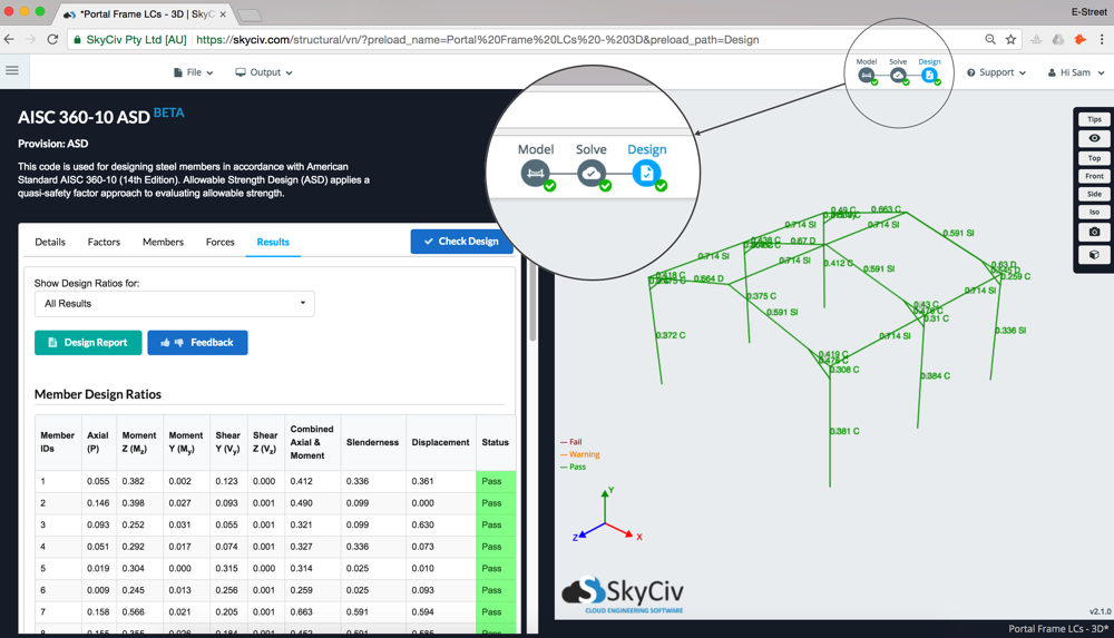
The member design modules are loaded into the software by clicking the “Design” bubble in the top right corner of the software:
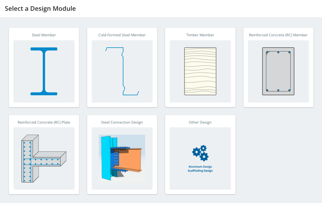
Selecting a design module will open up a tab on the left side which contains all of the information and input required to run a design check. For the most part, everything has been imported directly from the sections and results, so you can run the design software by clicking the blue “Check Design” button.
Using the Module
Details
The first tab Details, simply allows the user to add in more information about the project such as Project Name, ID, designer and notes. These will appear at the top of the reports generated by the design module.
Factors
Factors are specific to each design module. Please visit the specific module documentation page for more information.
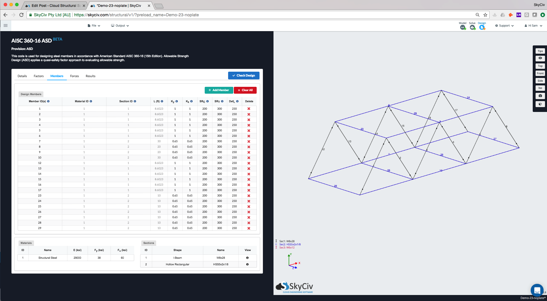
Members
The Members tab contains all the input related to the each of the members to be designed in the module. These may contain specific parameters for each design software (hover over the tooltips for more info). These can be changed at anytime by changing the values in the cells.
The Design Member table contains all the members, their materials, section IDs, length and their limit factors that have been automatically populated from the model.
Joining Members
In some circumstances it’s necessary to design multiple members as single Design Member. This can be done by entering the Member Ids as a comma-separated list (for instance 1, 2, 4 will design members 1, 2 and 4 together). A range of member IDs can also be inputted (for instance 1-3 will design members 1, 2 and 3 together), combinations of single IDs and range IDs can also be used (for instance 1, 3-5 will design members 1, 3, 4 and 5 together).
Flexural Buckling
For single members the braced length and effective length factors can be set for their respective axes:
- Ly (braced length along y axis),
- Lz (braced length along z-axis),
- Ky (effective length factor along y-axis),
- Kz (effective length factor along z-axis)
For combined members the critical braced length (the one which will govern the design) should be entered manually.
For combined members the critical effective length factor (the one which will govern the design) should be entered manually.
Flexural-Torisional Buckling
For combined members the critical unbraced length of the beam should be entered manually:
- Llt (critical unbraced length of beam)
Slenderness
If this check is not required increasing the default values for members in tension and compression to above the value required to pass.
Deflection
Deflection is checked against the local displacement of each member relative to it’s globally displaced position along the axis of interest. This check is not required in all circumstances, if your design is failing due to this check you can decrease the limit to 1 to ensure that the check does not fail.
Sections and Materials
The materials and Sections (in the lower tables) are automatically populated from the model. You can hover over the icon for more information.
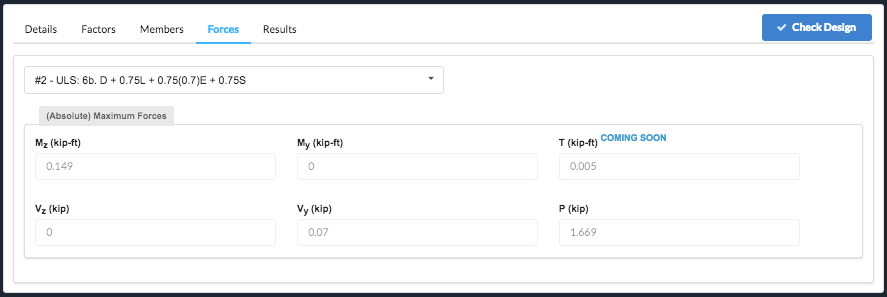
Forces
Internal member forces are automatically imported from the structural analysis, this includes load combinations. The software will display each of the forces as per the selected load combination. The software will design check based on the worst case for each member and load combination.
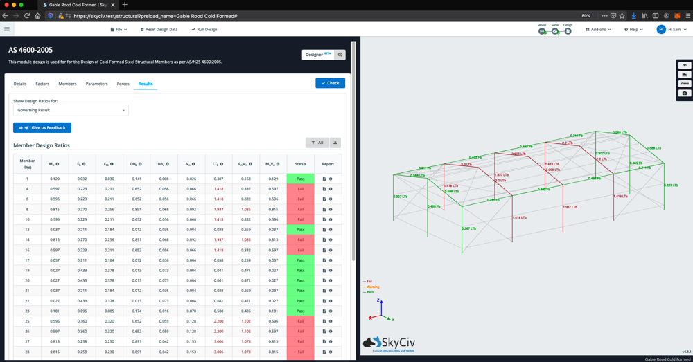
Results
There are a number of ways to review the results of your design check:
-
- Tabulated Results – these will highlight the members as Pass or Fail in green or red, respectively. You can export these results as a CSV
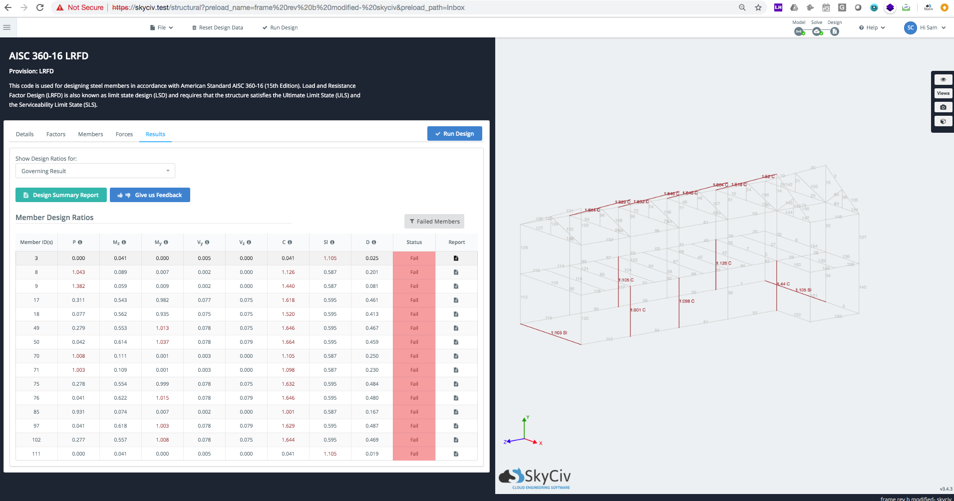
- Graphical Results – on the right side, the structure will display the green and red colouring of each member as well as the highest capacity ratio of all the results. For instance, if the max capacity ratio is 1.321 for Slenderness, it will display 1.321 Sl – it will display as red as the ratio is > 1. The result colours, are represented as follows:
- Green: The maximum member utility ratio is < 1, and therefore passing the requirements of this standard
- Orange: The maximum member utility ratio is between > 0.95 but < 1. It is still passing, but close to full utilization
- Red: The maximum member utility ratio is > 1, and therefore failing the requirements of this standard
- Gray: A grey member will indicate that a design check was not performed on this member. This could be for a number of reasons, including; this section shape is not supported by this design code, the member is a custom section, the material inputs were not specified correctly.
- You can also select specific design ratios, by changing the dropdown list of “Show Design Ratios for:” – this will show All Results (maximum capacity ratio) by default.
- Reporting – You can export a PDF summary report of the design checks at anytime.
Filtering
Sometimes on larger structures you might want to filter out certain members to clearly identify members of significance. For instance, isolating any failing members. To filter specific members based on pass/fail criteria or sections, click the filter icon above the results table:
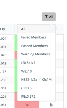
Selecting Failed Members will filter and display only those members that are failing:
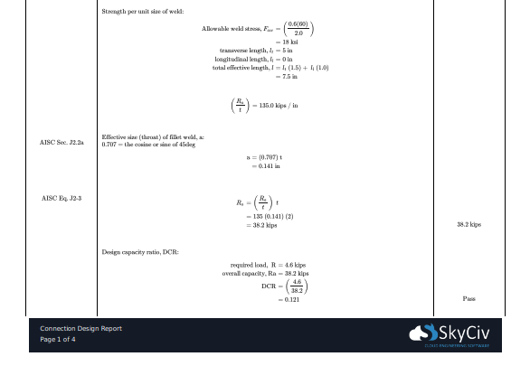
Full Design Reporting
Full design reporting, including step by step calculation reports for each member, are available for certain steel member design codes. These reports show full references, assumptions, calculation decisions and utility ratios, so engineers can take a closer look at what the software is doing. Available for all above design codes.