Powerful non-linear Reinforced Concrete (RC) Design for general sections
Introduction
SkyCiv General Section Designer (GSD) is the design tool for general case of section capacity calculation based on any kind of section shapes, reinforcement pattern and load interactions. The software is capable of the following:
- Design of reinforced concrete sections of beam and columns in case of tension-compression with bi-flexure;
- Design of typical and general sections with default reinforcement arrangement;
- Design coefficients for materials and reducing factor according to the wide variety of codes;
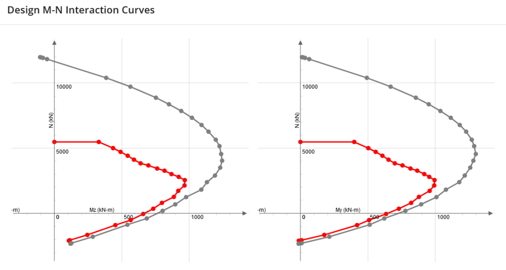
- Investigation of section capacity using design (with design coefficients and reducing factor) and nominal (without them) interaction diagrams My-Mz-N for arbitrary angle of bending plane;
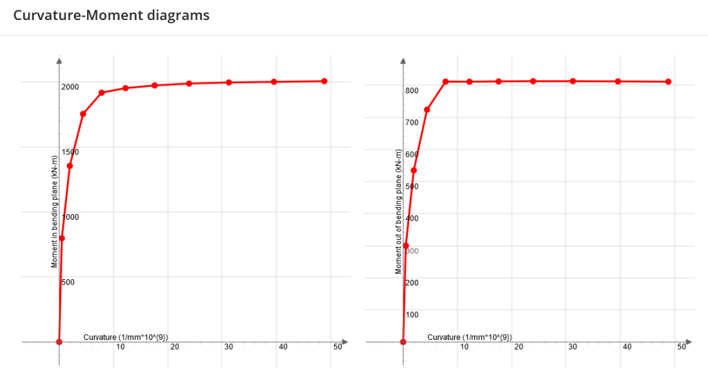
- Curvature – Bending moment (in and out of bending plane) for arbitrary bending plane and predefined axial force;
- Capacity calculation is based on pre-defined (or user-defined) stress-strain diagrams for both concrete and reinforcement.
SkyCiv General Section Designer (GSD) with a custom shape and reinforcement
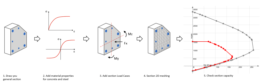
General Workflow
Generally the steps follow – (1) draw section, (2) add rebar, (3) add loads (4) solve. There are additional controls for concrete and reinforcement materials and can be defined with true strain-strain curves, representing real behavior of materials. Loads can be applied like combination of axial load and bending moments about two major axes. Load Cases can be defined as many as necessary. Then section is approximated internally by 2D mesh (done by program automatically) and performed analysis. As the results user receives section capacity due to action of applied loads. Each Load Case result can be checked in detailed report with graphical review of section stress-strain status. Also user is able to generate 3D strength surfaces plot My-Mz-Fx.
Usage Instructions
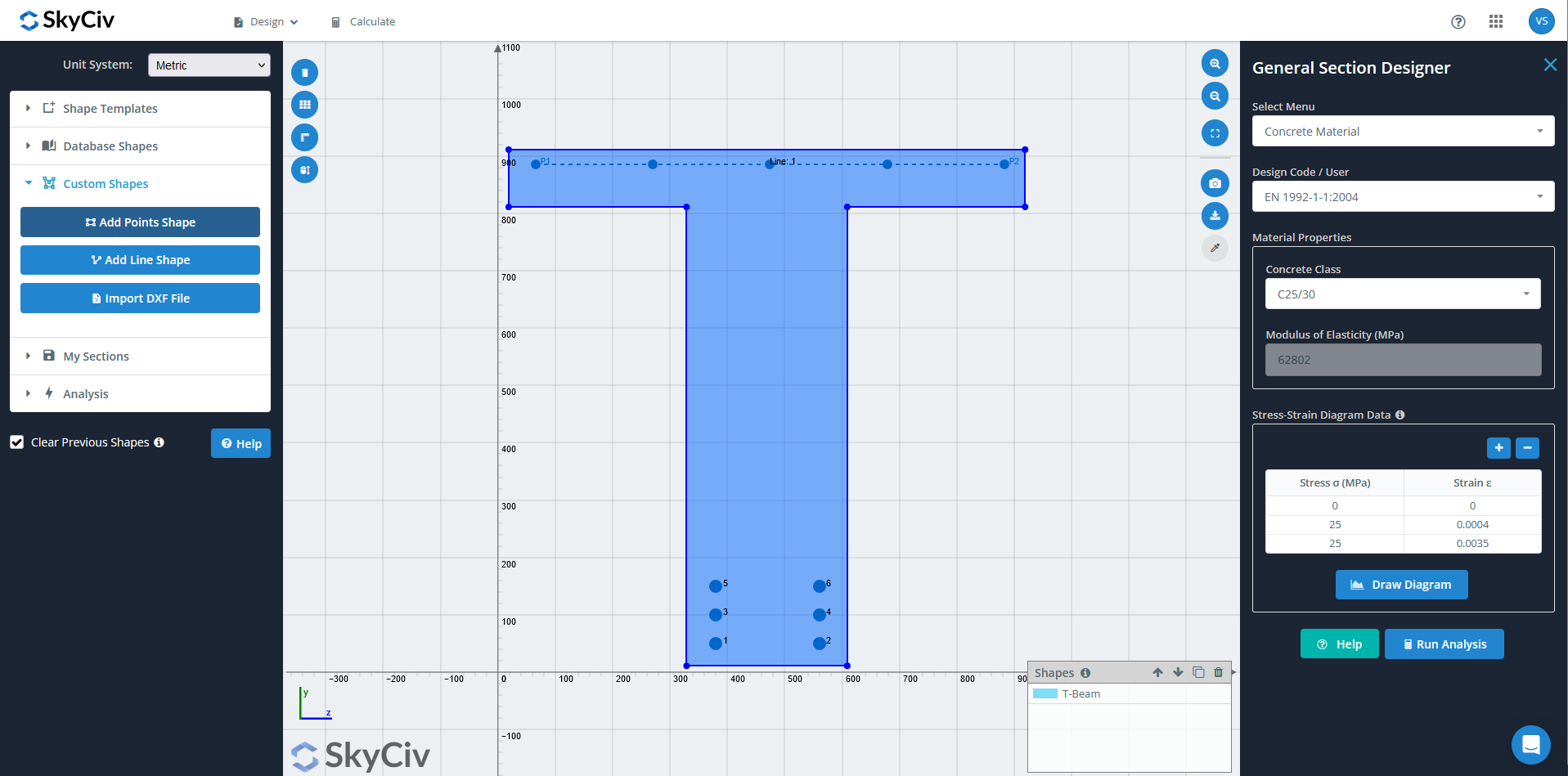
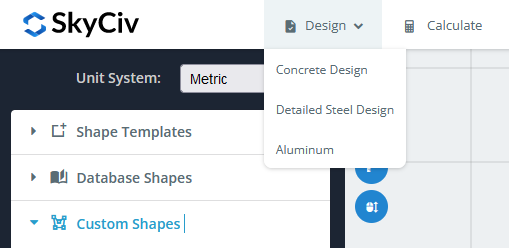
The GSD is accessed through the Section Builder from within the Dashboard. Select Unit System (Metric or Imperial) and select your section from Section Templates or define Custom Section via Points Shape, Line Shape or Import DXF file.
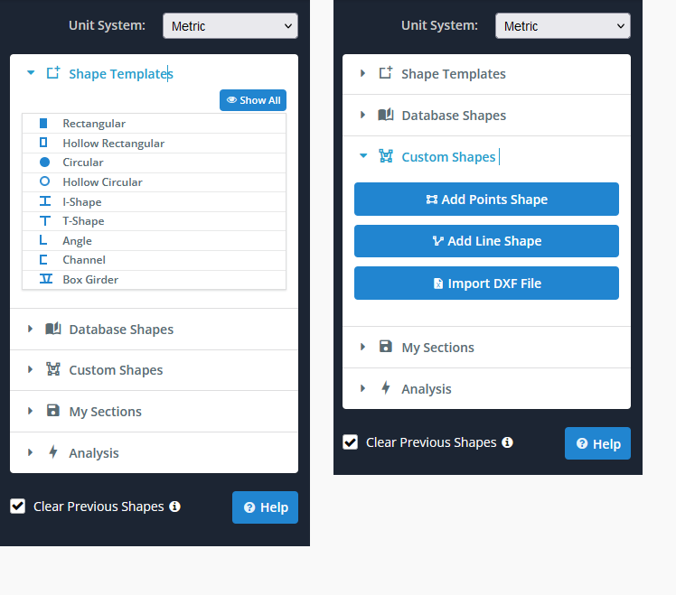
Model any Section!
The section builder uses powerful FEA to analyze the cross section, so you can design just about any section. Add in a rectangular, circular,T-shape, or even custom shapes (using points, lines or DXF) to design your custom shapes!
From top menu select Design > Concrete Design.
This will open the right menu to allow you to control the input for the concrete and steel reinforcement. The following input can be controlled from the dropdown:
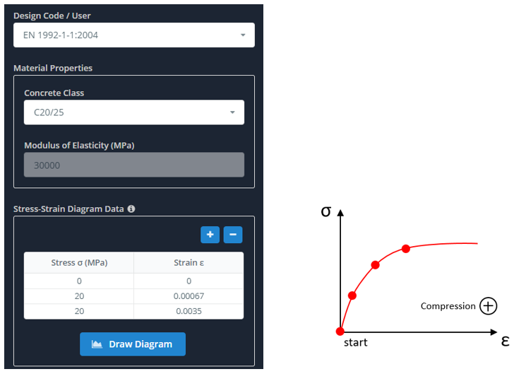
Concrete Material
Concrete Material allows users to select template material based on design code, or to define custom concrete material like initial Modulus of Elasticity and Stress-Strain Diagram values. The program assumes that concrete is inactive in tension such that tensioning strains in concrete produces zero stress – which is considered a common assumption for RC design practice. So, in Stress-Strain Diagram Data you only put the compression branch of diagram with positive sign values. The following image shows a proper definition:
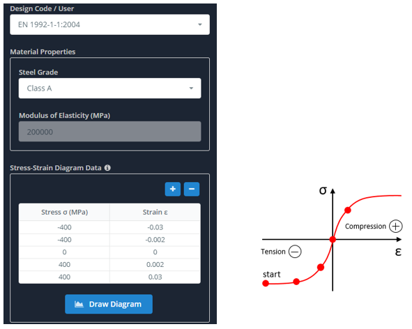
Rebar Material
The dropdown Rebar Material you are also able to select either template materials based on design code (e.g. EN 1992 – Class A) or to define your own custom parameters. Rebar assumes both compression and tension during section loading. So, two diagram branches must be defined in Stress-Strain diagram with the plus sign for compression case and minus sign for tension case. The following image shows a proper definition:
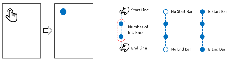
Rebar Position (Defining Reinforcement)
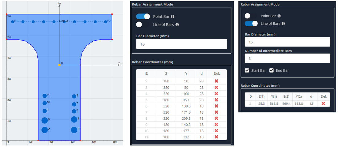
The dropdown Rebar Position you define your reinforcement pattern in your section. We currently have two options to define reinforcement: Point Bar and Line of Bars. With Point Bar option you can click anywhere inside a section and a rebar with predefined diameter will be displayed. At the same time coordinates of this rebar will be displayed in the Rebar Coordinates table below for your control. This gives you possibility to edit existing bar position or it diameter, or even remove it from section. With the second option, Line of Bars, you can click the starting position of line and an ending position of line. Use the the predefined number of bars and diameter to control what is applied. You can also control the start and end of each bars-line to keep only intermediate bars. All the defined line data are reflected below in the Rebar Coordinates table for editing. Below is an example; the bottom of the section has point bars, while the top is using the Line of Bars function:
Section Loads
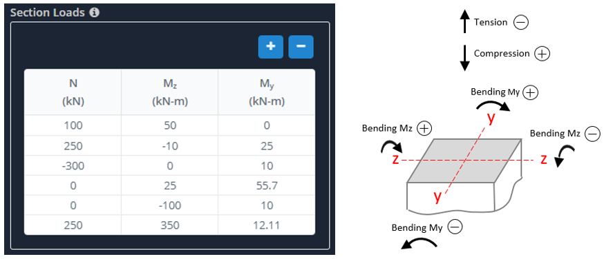
The dropdown Section Loads allows users to define all the necessary Load Cases for section strength check. Loads can be input manually by typing corresponding value in cells or loads can be copied and pasted inside the table from Excel sheet. Follow the image guide for a proper definition of loads with corresponding signs.
Analysis
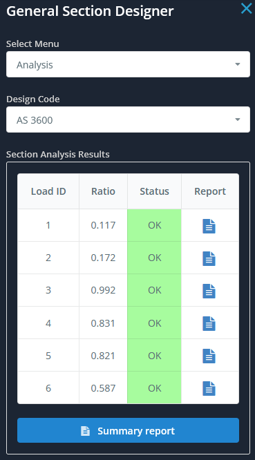
After inputting all your rebar and material information, select design code and click Run Analysis. In the Section Analysis Results table briefly reflected section capacity information for each Load Cases. Each row in the table displays the Load ID, Capacity Ratio value (less 1.0 means that equilibrium is obtained and strength is validated, otherwise not), result status (OK – passed, NG – section is not good). Also you can create Summary Report with all info about materials, rebar position, load cases and design diagrams.
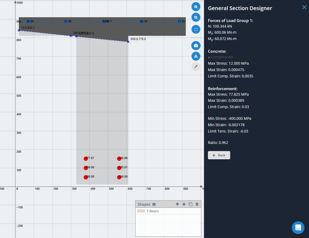
Clicking the Report icon in the row will display the dialog box with detailed report of that particular load case – showing the stress-strain status of your section (if Ratio > 1 it shows results for limit state). Both the compressed concrete area (dark gray color) and tensioned concrete area (light gray color) are displayed, as well as compressed rebar (blue color) and tensioned rebar (red color). The report also displays the max/min stresses and strains in concrete and rebar, limited values of strains and capacity ratio.
There are two options for diagram analysis: interaction diagrams and curvature-moment diagrams. You may input angle of bending plane vector (from 0 to 360 degrees) that directed at compression area and get both types of diagrams. For curvature-moment diagrams you may input axial force acted in section.
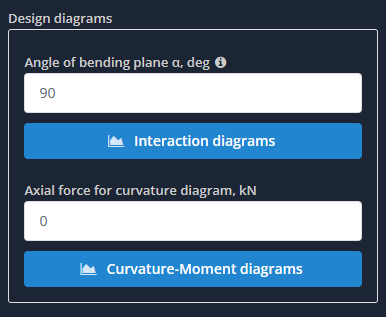
If you’ve selected design code option, you’ll obtain design diagrams too.
Also, all diagrams can be downloaded in *.csv format.