List of Contents
- What is a Cantilever Beam?
- Cantilever Beam Equations and Manual Calculations
- Cantilever Beam Design
- Cantilever Beam Software
Cantilever Beam Definition: What is a Cantilever Beam?
A cantilever beam is a structural element that extends horizontally and is supported on only one end. The unsupported end is known as the cantilever, and it extends beyond the support point. Cantilever beams are often used in construction to support balconies, roofs, and other overhangs. They can also be used in bridges and other structures to extend the deck out over a waterway or other obstacle.
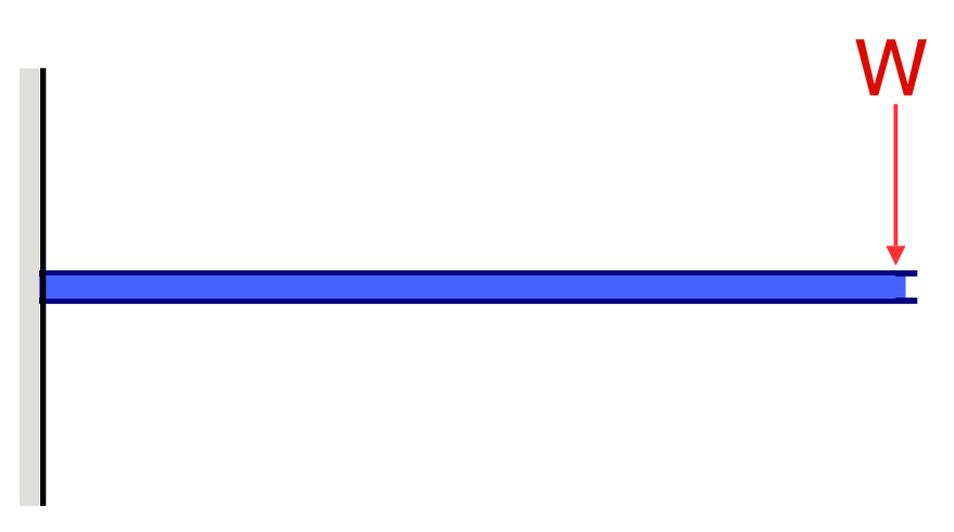
Cantilever beams are members that are supported from a single side only – typically with fixed support. In order to ensure the structure is static, the support must be fixed so that it is able to support all forces and moments in all directions. A cantilever beam is usually modeled like so, with the left end being the support and the right end being the cantilevered end:
Cantilever Beam Equations
There are a range of equations for how to calculate cantilever beam forces and deflections. These can be simplified into simple cantilever beam formula, based on the following:
Cantilever Beam Deflections
Taken from our beam deflection formula and equation page. Cantilever Beam equations can be calculated from the following formula, where:
- W = Load
- L = Member Length
- E = Young’s Modulus
- I = the beam’s Moment of Inertia
|
 |
 |
 |
 |
 |
Cantilever Beam Moments
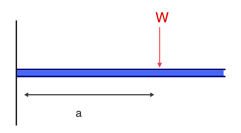
So how do we calculate the maximum bending moment force of a cantilever beam? You can do this using the same method as shown in our how to calculate bending moment in a beam article. However, there are short hand equations you can use. For instance, the equation for the bending moment at any point x along a cantilever beam is given by:
\(M_x = -Px\)
where:
\(M_x \) = bending moment at point x
\(P \) = load applied at the end of the cantilever
\(x \) = distance from the fixed end (support point) to point of interest along the length of the beam.
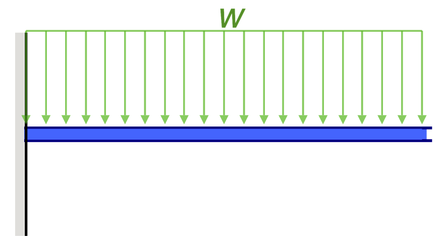
For a distributed load, the equation would change to:
\(M_x = – ∫wx\) over the length (x1 to x2)
where: w = distributed load x1 and x2 are the limits of integration.
This equation is valid for a simple cantilever beam with a point load or a uniformly distributed load applied at the free end of the beam. It should be considered that cantilevers beam can have complex loading and boundary conditions, such as multiple point loads, varying distributed loads, or even inclined loads, in those cases the above equation might not be valid, and a more complex approach might be required, it’s where the FEA comes in handy.
Cantilever Beam Stress
How to calculate stress in a cantilever beam? Cantilever Stress is calculated from the bending force and is dependent on the beam’s cross-section. For instance, if a member is quite small, there is not much cross-sectional area for the force to spread across, so the stress will be quite high. Cantilever beam stress can be calculated from either our tutorial on how to calculate beam stress or using SkyCiv Beam Software – which will show the stresses of your beam.
It’s useful to note that cantilever beams typically result in tension on the upper fibres of the beam. This means that in the case of a concrete cantilever beam, primary tensile reinforcement is typically required along the upper surface. This is in contrast to a conventional concrete beam supported at both ends, where primary tensile reinforcement would typically exist along the bottom surface of the beam.
Cantilever Beam Reaction Forces
Cantilevers deflect more than most types of beams since they are only supported from one end. This means there is less support for the load to be transferred. Cantilever beam deflection can be calculated in a few different ways, including using simplified cantilever beam equations or cantilever beam calculators and software (more information on both is below). The equation for the reaction at a fixed support of a cantilever beam is simply given by:
Reaction Force in Y \( = R_y = P\)
Moment Force about Z \( = {F}_{y} = Px\)
where:
\(F_y \) = reaction force in the Y direction at support A (the fixed support)
\(M_z \) = reaction moment about Z at support A (the fixed support)
\(P \) = the load applied at the end of the cantilever beam
\(x \) = distance of point load from support
This equation applies when the load is a point load on a cantilever. When the load is distributed, it is the summation of all forces in the vertical direction that needs to be zero. The equation becomes:
\(∑F_x = 0\)
Where the reaction force would be the algebraic sum of all the vertical forces acting on the structure. This equation assumes that the support is a fixed support, meaning that it does not have any rotation or translation. If the support has some degrees of freedom, the equation would change and become more complex. It’s important to keep in mind that this equation is just one step in analyzing a structure, in the design process of a real structure, several considerations such as load combinations, safety factors, material properties, etc. will be taken into account before finalizing a design.
Cantilever Beam Design
When designing a cantilever structure, several important factors should be considered:
- Loads: The cantilever must be able to support the applied loads, including the weight of the structure itself and any additional loads such as wind, snow, and seismic loads. The loads should be analyzed and distributed appropriately throughout the structure.
- Strength and stiffness: The cantilever must be strong and stiff enough to resist deflection, buckling, and other types of failure. The properties of the materials used, such as the modulus of elasticity and yield strength, will affect the strength and stiffness of the structure.
- Stress concentration: The stress concentration at the fixed end of the cantilever must be taken into account in the design to prevent failure. Stress concentration can be reduced by using larger cross-sections or by using fillets or rounded corners.
- Deflection: The deflection of the cantilever under load should be analyzed to ensure that it remains within acceptable limits, both for structural safety and also for aesthetic reasons.
- Durability: The structure should be designed to last for the intended service life with minimal maintenance required. This includes considering factors such as corrosion, fatigue, and the effects of weathering.
- Safety factors: Safety factors should be considered and included in the design to ensure that the structure can withstand unexpected loads or other unforeseen circumstances.
- Construction methods: The design must take into account the method of construction to be used, whether it be pre-fabricated, cast-in-place, etc. This will affect the type of connections and the overall layout of the structure.
- Cost: Design should consider both initial cost and long-term maintenance costs.
- Building codes and regulations: The design must be compliant with the relevant building codes and regulations in the jurisdiction where the structure will be built. For instance, if the beam is steel and based in the US, it should comply with the requirements of AISC 360 Design Checks
It’s important to keep in mind that this is not an exhaustive list, and the specific requirements and considerations for a cantilever design may vary depending on the particular structure and its intended use. A structural engineer with expertise in cantilever design would take all of these factors into account and more, to ensure that the design is safe and effective.
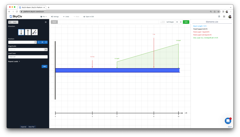
Cantilever Beam Software
SkyCiv Beam Analysis Software allows users to analyze cantilever beam structures easily and accurately. You can get a simplified analysis of your beam member, including reactions, shear force, bending moment, deflection, stresses, and indeterminate beams in a matter of seconds. Apply any combination of loads and complete a full design as per American, European, Australian, Canadian Standards, to name a few!
If you want to give it a try first, Free Online Beam Calculator is a great way to start, or simply sign up for free today!