A guide to modeling a Concrete Structure in SkyCiv Structural 3D Analysis and Design software
Brief
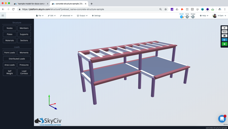
In this article we will demonstrate a step-by-step guide of how to model concrete structure, covering topics such as nodes, members, plates, meshing plates and materials. Since we have a large number of users designing concrete structures, we thought it might be a good idea to go through a start-to-finish example of how to model a simple concrete frame, with a few slabs and a cantilever balcony. We will mainly cover the modeling aspects and not so much the actual design. The above sample structure is built is SkyCiv Structural 3D – analysis and design software that is fully accessed through your web browser.
For full analysis and design features, try our Concrete Structure Design Software to complement your modeling workflow.
Sample Model: concrete-structure-sample-docs.s3d
Watch the Tutorial Video:
Step 1: Define the nodes and members
How you define your nodes is usually based on preference. Some users swear by the datasheet (or copying nodes directly from Excel), whereas some users, like me, prefer to use the inbuilt modelling functions of the software. In this case, I will define my nodes and members using the Pen Tool and a few of the right click functions. Remember: you don’t have to use the pen tool here, you can simply enter the nodes of the structure through the left field and join them by click and dragging using the crosshair.
Use the pen tool to outline the general shape of the structure:
Start by modelling the outline of the structure. We’re going to build a simple 8 x 5.5 x 20m. As this structure doesn’t have any complex members, it would be easy to use the pen tool to model out the structure:
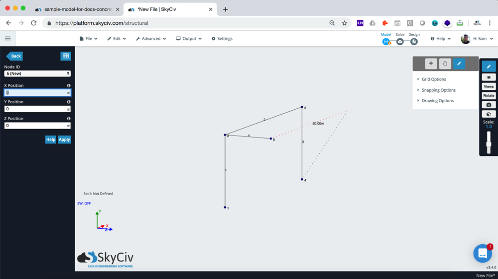
You can also use the pen tool to snap from a midpoint, so you don’t need to manually calculate these positions. This is useful when building our cantilever:
Assign different sections:
Since we’re going to have 3 sections: (1) concrete columns, (2) cross beams and (3) outer beams, we should start defining the different section IDs. The way I like to do this, is using the CTRL + Click drag function (drag to the right to highlight anything in contact with the selection box). To do this, I will turn my crosshair back on (i.e. turn off the pen tool), then select the sections I want to change, then click members to multi-edit a batch of elements:
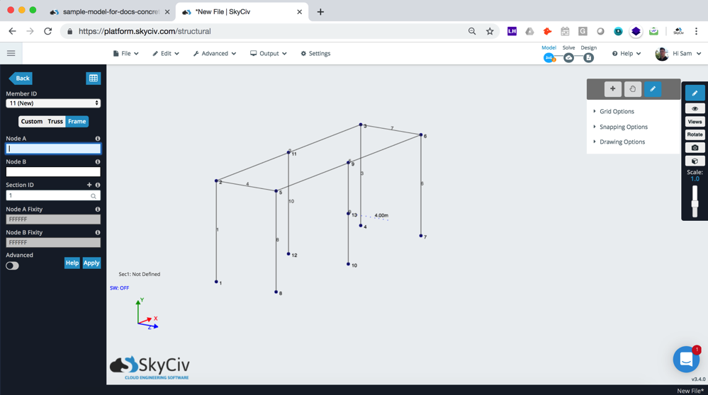
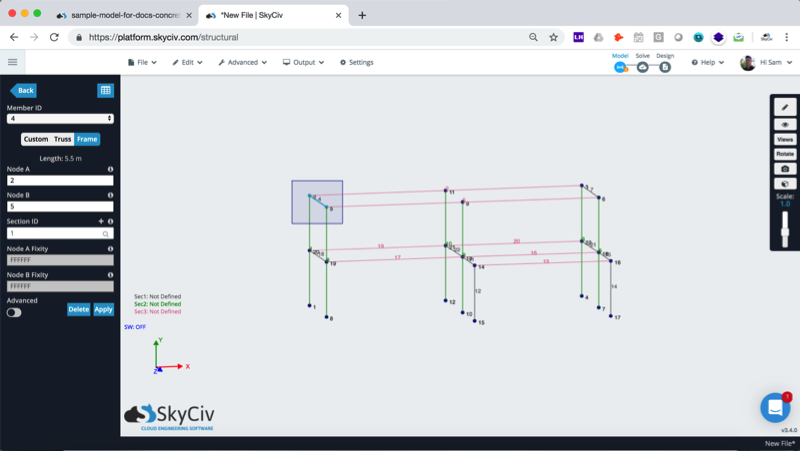
Add multiple beams:
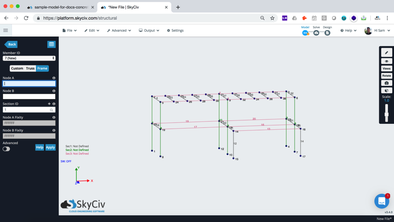
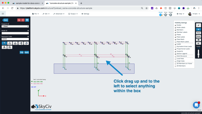
Now we want to add 10 beams, spaced 2m apart along the top beams. We could model this manually, but a faster way would be to use the duplicate functionality to copy across a single beam – which is much faster. The duplicate will carry with it any attributes (section ID, offsets etc…). Here are the steps of how to use this operation. Start by using inclusive selecting (CTRL + Drag left) to isolate the part of the model you wish to duplicate. This will only select what is within the box, making it easier to isolate the members and nodes you wish to duplicate:
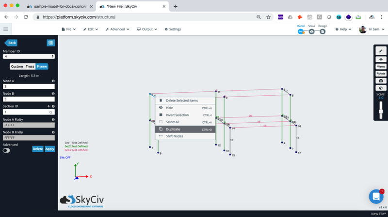
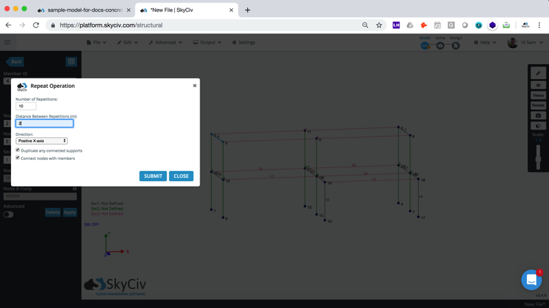
After right clicking the highlighted element, and selecting the duplicate option, you will be presented with the following popup. Here you will enter the direction and number of repetitions to add:
Add Supports:
To add supports, I am going to use another shortcut but holding CTRL and click-dragging the mouse to implement the inclusive selection box. From here you can simply click the Node ID box to include all the selected nodes:
Step 2: Assign Sections and Material Data
We now want to define the sections and their materials. We need to define what their cross sections are so that the software can understand the material strength and geometric properties of our beams and columns. This is required information for the software to calculate results such as deflection and stresses as they define what the member’s E (Young’s Modulus) and I (Moment of Inertia) among other sectional properties. In this case, we will apply 3 sections to represent the three sections we defined in our previous step.
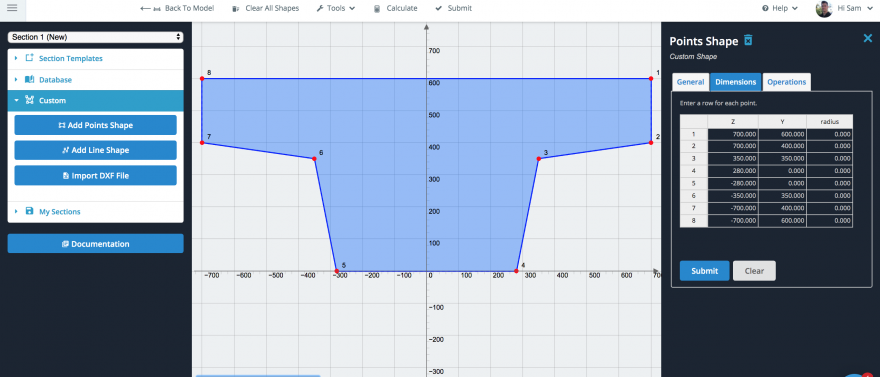
Our beams will be a custom shape, so that we can add and design the reinforcement of these sections in the SkyCiv General Section Designer.
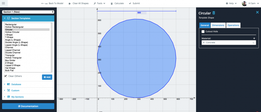
We will also add a concrete column by adding a circular shape of 600mm and changing the default material from Structural Steel to Concrete. We can add a custom material by clicking the ‘+’ sign and opening the SkyCiv Material Database. In our example we are just going to use the standard concrete material provided by default, but you can change these properties at anytime under Materials in the main UI.
Step 3: Add Plates (concrete slabs)
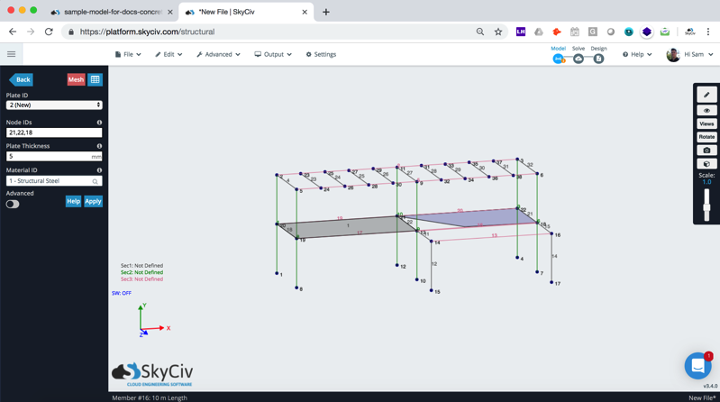
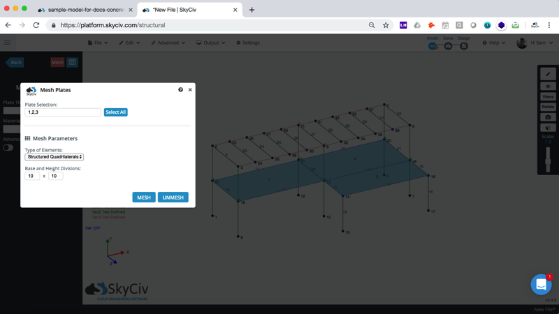
We can add plates a number of different ways. Since SkyCiv Plates are not limited by the number of nodes, we could enter the entire plate in one go, then use the Quadrilateral Meshing feature to automatically mesh the entire plate. This is helpful if you have curved or irregular plates. In our case, the structure is fairly regular so we can build three rectangular plates like so:
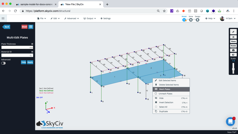
We then hold CTRL and multi select all three plates, so we can mesh them all at once. This is really important as it tells the software we want the plates to be connected by common nodes.
Inspecting our Mesh:
Inspecting our Mesh we can see a few important things:
- There are nodes along the members. Since the members are continuous so they will automatically pick up and connect to any intermediate nodes. This ensures our plate is connected to the members correctly.
- The plates are joined by common nodes
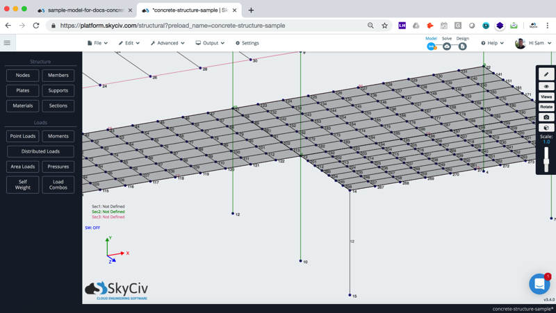
Note: Even though there some inconsistencies in the mesh (the 3rd plate mesh, is inconsistent with the first two), this is a first iteration of the design, we only really need to see if the strength of the members is met. We can improve on this later by re-meshing our plates (right click – Mesh), to make the mesh more consistent across the third plate.
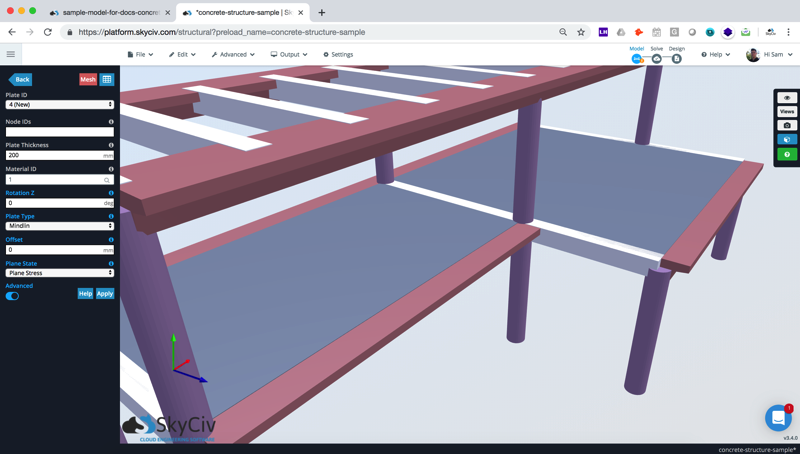
Edit materials, thickness and offset of our plates:
Personally, I like to use the 3d renderer to review and edit certain parts of the model. It helps me ensure the model dimensions are built correctly (for instance a really thin section will be very obvious). Take our plates for instance; after opening the 3D Renderer I realised I forgot to adjust the thickness of the plate from the default value:
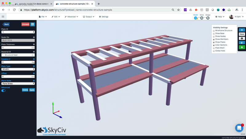
From here, I assigned the 3 plates with a 200mm thickness, changed the material to Concrete and also offset the plate by -140mm (this will shift up the plate as the local axis of the plate is Z down):
We can also see this by turning on Wireframe mode and selecting the elements that you’re looking to edit (in this case I CTRL + clicked the internal plate and the two outer beam members):
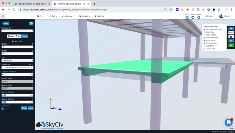
There you have it, you can then assign some loads or apply a self weight and hit Solve to run your analysis.
Further Concrete Design and Analysis:
RC Beam and Column Design
To further the design of this structure, users can design the columns, shear walls and beams as per ACI 318, AS 3600, CSA A23 and Eurocode 2 for Reinforced Concrete Design. Click here to learn more about how to get started designing your concrete beams and columns in Structural 3D.
Foundation Design
The foundations of this building can also be designed as per ACI 318, AS 3600 concrete design standards with SkyCiv’s built-in Foundation Design Software.
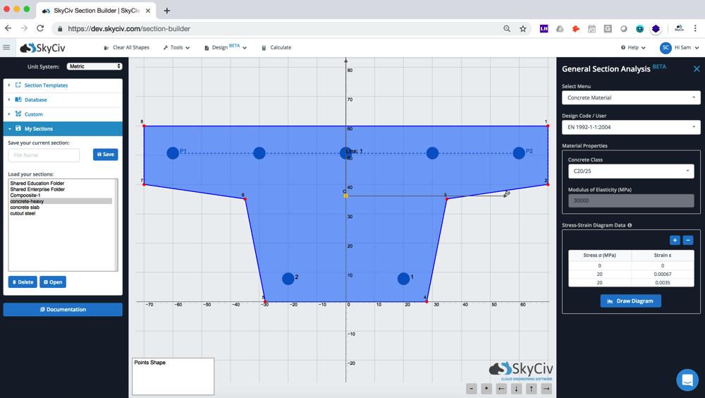
General Section Designer
Custom beams and column shapes can be designed using the SkyCiv General Designer. Input your loads from the above analysis into the GSD to get the moment capacity and utility ratios of any custom members you might be designing:
Related tutorials:
For an updated tutorial, check out or example on How to Model a Concrete Structure Walls and Slabs with SkyCiv Structural 3D.