
Figure 1: Book 1 (left), Book 2 (center) and Book 3 (right)
Information presented on this page is intended to demonstrate the section design convergence of ACI 318-2014 provisions for isolated foundations that can be achieved with SkyCiv. All examples are taken from the following references:
Book 1: Jack O.McCormac, Russell H.Brown. Reinforced Concrete Design (Tenth Edition), 2015.
Book 2: American Concrete Institute. ACI SP-17(14) The Reinforced Concrete Design Handbook, 2016.
Book 3: M. Nadim Hassoun, Akthem Al-Manaseer. Structural Concrete Theory and Design (Sixth Edition), 2015.
Example # 1 Design of axially loaded Isolated Footing.
reference: Book 2, pp.425.
DESCRIPTION
An Isolated foundation is subjected to three (3) static load cases (Dead, Live and Earthquake load). The resulting shear, moment, load transfer and development length are compared with manual calculations. The foundation model lies in the X-Z plane.
GEOMETRY AND MATERIAL PROPERTIES
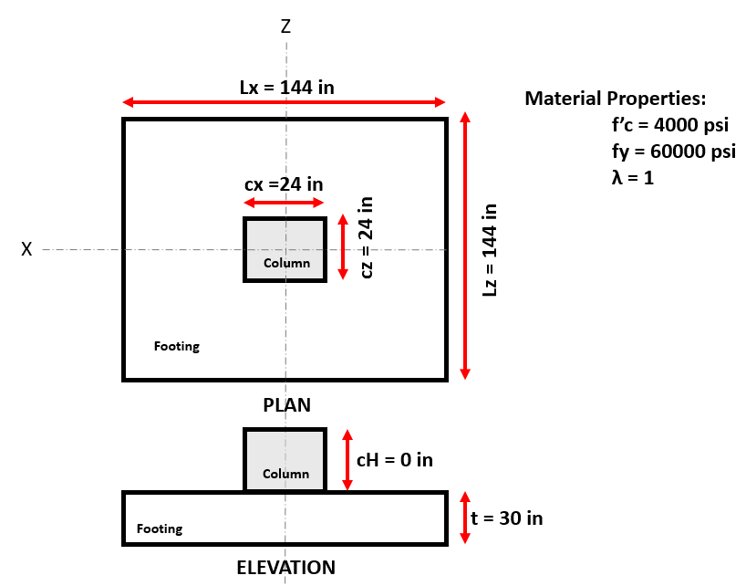
Figure 2: Footing model and material properties of example #1
LOADING
Three static loads cases are considered:
\( \text{DL} = 541.00 \text{ kips} \)
\( \text{LL} = 194.00 \text{ kips} \)
\( \text{ E} = 18.00 \text{ kips} \)
The results of service and factor load combination are in computed in reference of ASCE/SEI 7-10.
ANALYSIS
The analysis is done using the rigid conventional method. See the Isolated Footing User Manual for more explanation on using SkyCiv Foundation.
RESULT COMPARISON
The most significant results are compared in the table below:
| Results | ||
|---|---|---|
| Parameter | Manual | SkyCiv |
| One way shear | ||
| Actual Shear | 231 | 229.9 |
| ΦVc | 348 | 348.36 |
| Two way shear | ||
| Bo | 198 | 200 |
| (a) 22.6.5.2 | 253.00 | 252.98 |
| (b) 22.6.5.2 | 379.50 | 379.47 |
| (c) 22.6.5.2 | 442.09 | 440.90 |
| ΦVc | 958.00 | 1005.06 |
| Flexure | ||
| Actual Moment | 1005 | 999.58 |
| Load Transfer | ||
| ΦBn | 2546 | 2545.92 |
| ldc = fy*Ψ/50*λ*√fc*db | 14.30 | 14.23 |
| ldc = 0.0003*fy*Ψ*db | 13.5 | 13.5 |
| Development Length | ||
| confinement term | 2.5 | 2.5 |
| ld | 28.5 | 28.5 |
Example #2 Design of axially loaded Isolated Footing.
reference: Book 1, pp.357.
DESCRIPTION
An Isolated foundation is subjected to two (2) static load cases (Dead and Live). The resulting shear , moment, load transfer and development length are compared with manual calculations. The foundation model lies in the X-Z plane.
GEOMETRY AND MATERIAL PROPERTIES
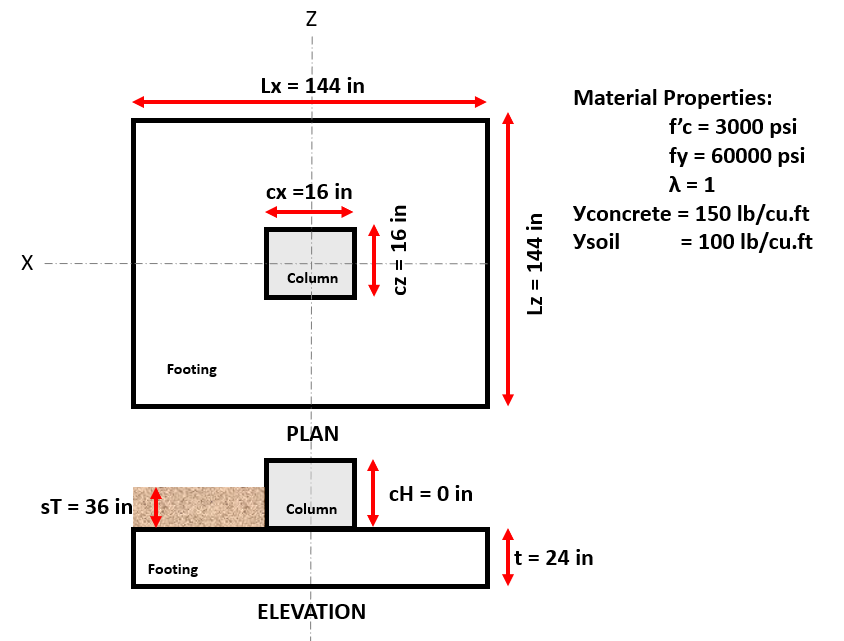
Figure 3: Footing model and material properties of Example #2
LOADING
Two static loads cases are considered:
\( \text{DL} = 200.00 \text{ kips} \)
\( \text{LL} = 160.00 \text{ kips} \)
The results of service and factor load combination are in computed in reference of ASCE/SEI 7-10.
ANALYSIS
The analysis is done using the rigid conventional method. See the Isolated Footing User Manual for more explanation on using SkyCiv Foundation.
RESULT COMPARISON
The most significant results are compared in the table below:
| Results | ||
|---|---|---|
| Parameter | Manual | SkyCiv |
| Soil Pressure | 6.12 | 6.12 |
| One way shear | ||
| Actual Shear | 121.62 | 121.70 |
| Two way shear | ||
| Bo | 142 | 140 |
| ΦVc | 442.09 | 440.9 |
| Flexure | ||
| Actual Moment | 404 | 404.91 |
| Development Length | ||
| confinement term | 2.5 | 2.5 |
| ld | 32.3 | 32.862 |
Example # 3 Design of axially loaded Isolated Footing.
reference: Book 1, pp.365.
DESCRIPTION
An Isolated foundation is subjected to two (2) static load cases (Dead and Live). The resulting shear, moment, load transfer and development length are compared with manual calculations. The foundation model lies in the X-Z plane.
GEOMETRY AND MATERIAL PROPERTIES
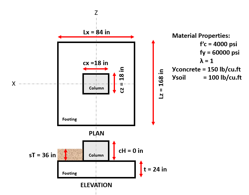
Figure 4: Footing model and material properties of example # 3
LOADING
Two static loads cases are considered:
\( \text{DL} = 185.00 \text{ kips} \)
\( \text{LL} = 150 \text{ kips} \)
The results of service and factor load combination are in computed in reference of ASCE/SEI 7-10.
ANALYSIS
The analysis is done using the rigid conventional method. See the Isolated Footing User Manual for more explanation on using SkyCiv Foundation.
RESULT COMPARISON
The most significant results are compared in the table below:
| Results | ||
|---|---|---|
| Parameter | Manual | SkyCiv |
| Soil Pressure | 4.17 | 4.17 |
| One way shear | ||
| Actual Shear | 152.49 | 149.02 |
| Two way shear | ||
| Bo | 142 | 144 |
| ΦVc | 415.58 | 413.16 |
| Flexure | ||
| Actual Moment | 643.9 | 644.53 |
Example # 4 Design of axially loaded Isolated Footing.
reference: Book 3, pp.461.
DESCRIPTION
A Isolated foundation is subjected to two (2) static load cases (Dead and Live). The resulting shear, moment, load transfer and development length are compared with manual calculations. The foundation model lies in the X-Z plane.
GEOMETRY AND MATERIAL PROPERTIES
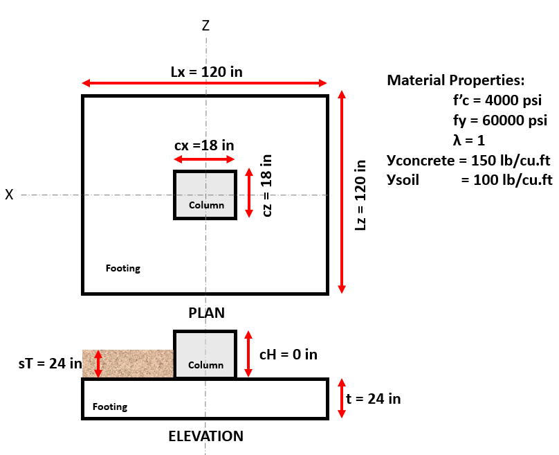
Figure 5: Footing model and material properties of example # 4
LOADING
Two static loads cases are considered:
\( \text{DL} = 245.00 \text{ kips} \)
\( \text{LL} = 200.00 \text{ kips} \)
The results of service and factor load combination are in computed in reference of ASCE/SEI 7-10.
ANALYSIS
The analysis is done using the rigid conventional method. See the Isolated Footing User Manual for more explanation on using SkyCiv Foundation.
RESULT COMPARISON
The most significant results are compared in the table below:
| Results | ||
|---|---|---|
| Parameter | Manual | SkyCiv |
| Soil Pressure | 6.14 | 6.14 |
| One way shear | ||
| Actual Shear | 161.2 | 161.17 |
| Two way shear | ||
| Bo | 150 | 152 |
| ΦVc | 554 | 552.44 |
| Flexure | ||
| Actual Moment | 554.5 | 554.52 |

Albert Pamonag
Structural Engineer, Product Development
B.S. Civil Engineering