A guide to the calculations required to design an isolated footing (EN 1992 & EN 1997)
The foundation is an essential building system that transfers column and wall forces to the supporting soil. Depending on the soil properties and building loads, the engineer may choose to support the structure on a shallow or deep foundation system³.
SkyCiv Foundation includes the design of isolated footing conforming to the Eurocode 2¹ and Eurocode 72.
Want to try SkyCiv’s Foundation Design software? Our tool allows users to perform Foundation Design calculations without any download or installation!
Design Parameters of an Isolated Footing
Calculations presented in SkyCiv use the prescriptive method based on EN 1997, where an assumed safe bearing pressure is used to size the foundation based on the serviceability limit state followed by the detailed structural design based on the ultimate limit state.
Dimension Requirements
To determine the dimensions of an isolated footing, characteristic actions, such as Permanent/Dead (Q), Variable/Live (Ql), Wind (Qw), Seismic (Qe), etc will be applied for the serviceability limit state. The critical loading arrangement/combination will be considered the design load, and is compared to the allowable soil pressure as shown in Equation 1. This example is limited to uniform soil pressure only.
\(\text{q}_{\text{a}} = \frac{\text{P}_{\text{n}}}{\text{A}} \rightarrow \) Equation 1
where:
qa = allowable soil pressure
Pn = unfactored design load
A = Foundation area
From Equation 1, qa are interchange with A.
\(\text{A} = \frac{\text{P}_{\text{n}}}{\text{q}_{\text{a}}} \rightarrow \) Equation 1a
At this point, the footing dimensions can be back-calculated from the required area dimension, A.
Flexure
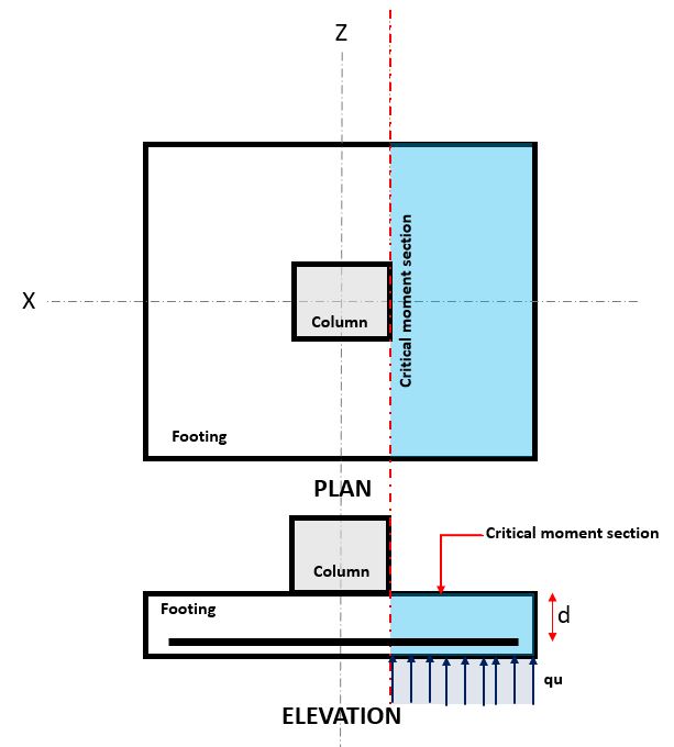
Figure 1. Critical Flexure Section
The Flexural limit state occurs at the Critical Flexure Section, located at the face of the column on top of the footing (Refer to Figure 1).
The Flexural Demand, or MED is located at the Critical Flexure Section (blue hatch area) indicated in Figure 1, and is calculated using Equation 2.
\( \text{M}_{u} = \text{q}_{u} \times \left ( \frac{l_{x}}{2} – \frac{c_{x}}{2} \right ) \times l_{z} \times \left ( \frac{\frac{l_{x}}{2} – \frac{c_{x}}{2} }{2} \right ) \rightarrow \) Equation 2
where:
qu = factored soil pressure, kPa
lx = footing dimension along the x-axis, mm
lz = footing dimension along the z-axis, mm
cx = column dimension along the x-axis, mm
The Flexural Capacity, or Mcapacity is calculated using Equation 3.
\(\text{M}_{capacity} = \frac{1}{\gamma_{S,pt}} \times f_{yk} \times A_{s} \times \left( d – \frac{s}{2} \right) \rightarrow \) Equation 3
where:
γS,pt = partial factor for reinforcing steel
lx = footing dimension parallel to x-axis, mm
lz = footing dimension parallel to z-axis, mm
d = distance from extreme compression fiber to centroid of longitudinal tension reinforcement, mm
As = reinforcement area, mm2
s = depth of equivalent rectangular stress block, mm
fyk = reinforcement strength, MPa
Moment Demand and Moment Capacity must be verified to meet the Ultimate Limit State of EN 1990:
\(\text{E}_{\text{d}} \leq \text{R}_{\text{d}} \rightarrow \) Equation 4 (EN 1990 6.4.1)
SkyCiv Foundation, in compliance of Equation 4, calculates the flexural unity ratio (Equation 5) by taking Flexural Demand over Flexural Capacity.
\( \text{Unity Ratio} = \frac{\text{Flexure Demand}}{\text{Flexure Capacity}} \rightarrow \) Equation 5
One-way Shear
The one-way shear limit state, also known as beam shear, is located at a distance “d” from the face of a column, at the Critical Shear Plane (Refer to Figure 2),
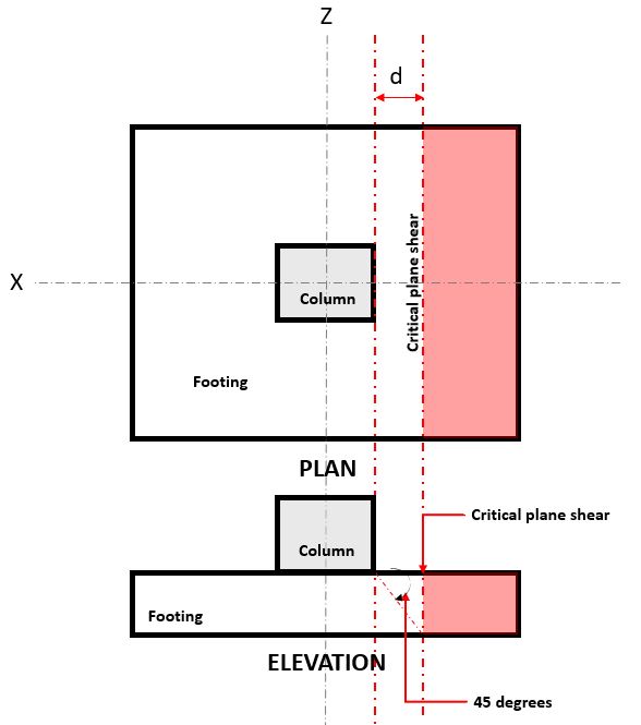
Figure 2. Critical Plane Shear of One-way shear
The One-way Shear Demand or VED is calculated assuming the footing is cantilevered away from the column where the area is (red) indicated in Figure 2.
The One-way Shear Capacity or VRd,c is defined as the shear resistance at the Ultimate Limit State (when no shear reinforcement is necessary) and calculated using Equation 6 per EN 1992, Section 6.2.2.
\(\text{V}_{\text{Rd,c}} = (\text{C}_{\text{Rd,c}} \times k \times (100 \times \rho_{1} \times \text{f}_{\text{ck}})^{\frac{1}{3}}) \times \text{b}_{\text{w}} \times \text{d} \rightarrow \) Equation 6 (EN 1992 Eq. 6.2.a)
with a minimum of
\(\text{V}_{\text{Rd,c}} = (0.035 \times k^{\frac{3}{2}} \times \text{f}_{\text{ck}}^{\frac{1}{2}}) \times \text{b}_{\text{w}} \times \text{d} \rightarrow \) Equation 9 (EN 1992 Eq. 6.2.b)
where:
CRd,c = recommended value of 0.18/γC
k = coefficient of 1 + √(200/d) ≤ 2.0
ρ1 = Asl / bwd ≤ 0.02
fck = specified concrete strength, MPa
bw = width of the footing, mm
d = distance from extreme compression fiber to centroid of longitudinal tension reinforcement, mm
Shear Demand and Shear Capacity must be verified to meet the Ultimate Limit State of EN 1990:
\(\text{E}_{\text{d}} \leq \text{R}_{\text{d}} \rightarrow \) Equation 4 (EN 1990 6.4.1)
SkyCiv Foundation, in compliance of Equation 4, calculates the one-way shear unity ratio (Equation 7) by taking Shear Demand over Shear Capacity.
\( \text{Unity Ratio} = \frac{\text{Shear Demand}}{\text{Shear Capacity}} \rightarrow \) Equation 7
Two-way Shear
The Two-way Shear limit state, also known as punching shear, extends it critical section to a distance “2d” from the face of the column and around the perimeter of the column. The Critical Shear Plane is located at that section of the footing (Refer to Figure 3).
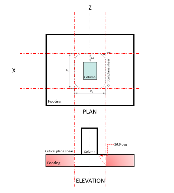
Figure 3. Critical Shear Plane of Two-way shear
The Two-way Shear Demand or VED occurs at the Critical Shear Plane, indicated in Figure 3, in accordance of EN 1992, Section 6.4.2.
The Shear Capacity or VRd,c, similar to one way shear capacity (when no shear reinforcement is necessary), is calculated based on EN 1992 Section 6.2.2 (Refer to Eq. 8).
\(\text{V}_{\text{Rd,c}} = (\text{C}_{\text{Rd,c}} \times k \times (100 \times \rho_{1} \times \text{f}_{\text{ck}})^{\frac{1}{3}}) \times \text{u}_{\text{1}} \times \text{d} \rightarrow \) Equation 8 (EN 1992 Eq. 6.2.a)
with a minimum of
\(\text{V}_{\text{Rd,c}} = (0.035 \times k^{\frac{3}{2}} \times \text{f}_{\text{ck}}^{\frac{1}{2}}) \times \text{u}_{\text{1}} \times \text{d} \rightarrow \) Equation 9 (EN 1992 Eq. 6.2.b)
where:
u1 = basic control perimeter, mm
Other variables similarly defined on One Way Shear Capacity.
In general, Shear Demand and Shear Capacity must meet the following equation to meet the Ultimate Limit State of EN 1990:
\(\text{E}_{\text{d}} \leq \text{R}_{\text{d}} \rightarrow \) Equation 4 (EN 1990 6.4.1)
SkyCiv Foundation, in compliance with Equation 4, calculates the two-way shear unity ratio (Equation 10) by taking Shear Demand over Shear Capacity.
\( \text{Unity Ratio} = \frac{\text{Shear Demand}}{\text{Shear Capacity}} \rightarrow \) Equation 10
NEW SkyCiv Foundation with FEA
As of March 2024, the Foundation Design Module has integrated the Finite Element Analysis (FEA) solver into its capabilities. This new feature allows users to conduct in-depth soil pressure and wood armer analyses while still performing all structural checks specified by EN 1992 and 1997, including all verifications mentioned above. Summary of the FEA Results is included in the comprehensive report.

Free Concrete Footing Calculator
Try SkyCiv Free Concrete Footing Calculator to design foundations for footings, combined footings, concrete piles, concrete pads, and more.
References
- Eurocode 2: Design of concrete structures – Part 1-1: General rules and rules for buildings (EN 1992-1-1:2004). European Committee for Standardization, 2004.
- Eurocode 7: Geotechnical design – Part 1: General rules (EN 1997-1:2004). European Committee for Standardization, 2004.
- Mosley, Bungey, and Hulse. Reinforced Concrete Design to Eurocode 2 (Seventh Edition), 2012.

Product Developer
BSc, MEng (Civil)