SkyCiv Foundation aims to provide a complete and a user-friendly interface to easily model pile foundations. Pile foundation module can be accessed by choosing “Piles” under the foundation type drop-down on the left side panel.
Navigational Tabs
The pile foundation interface comprises 6 main navigation tabs. These tabs are located on the left side panel and are composed of the following:
- Geometry
- Soil Configurations
- Materials
- Loads
- Reinforcements
- Design Parameters
This documentation contains a detailed guide on using the navigational tabs to build your model.
1. Geometry
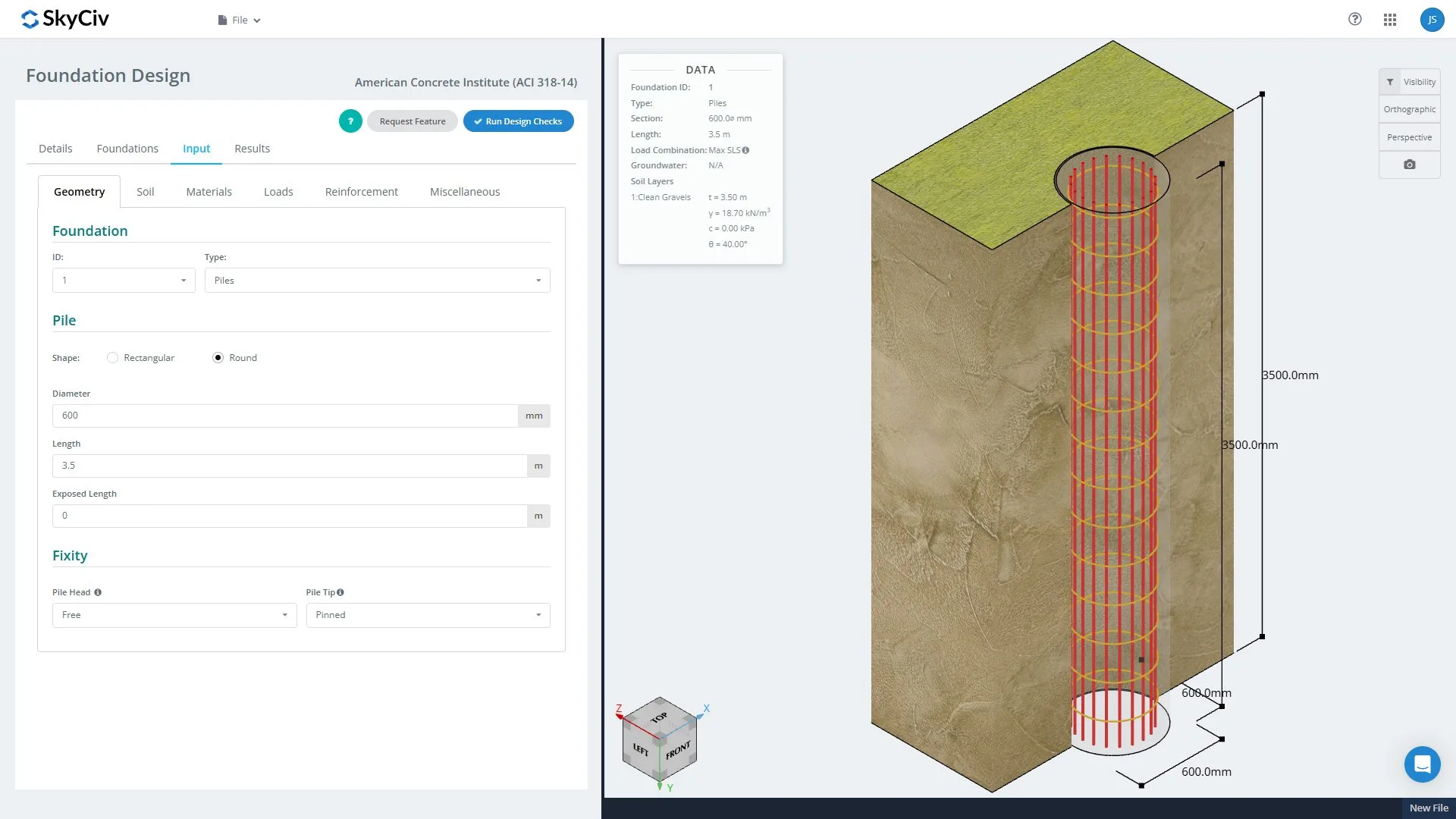
This tab configures all the details for the concrete pile’s dimensions. It includes the shape, depth, and width of the cross-section, the length of the pile, the position of the pile head, and the boundary conditions at the head and tip of the pile.
2. Soil Configurations
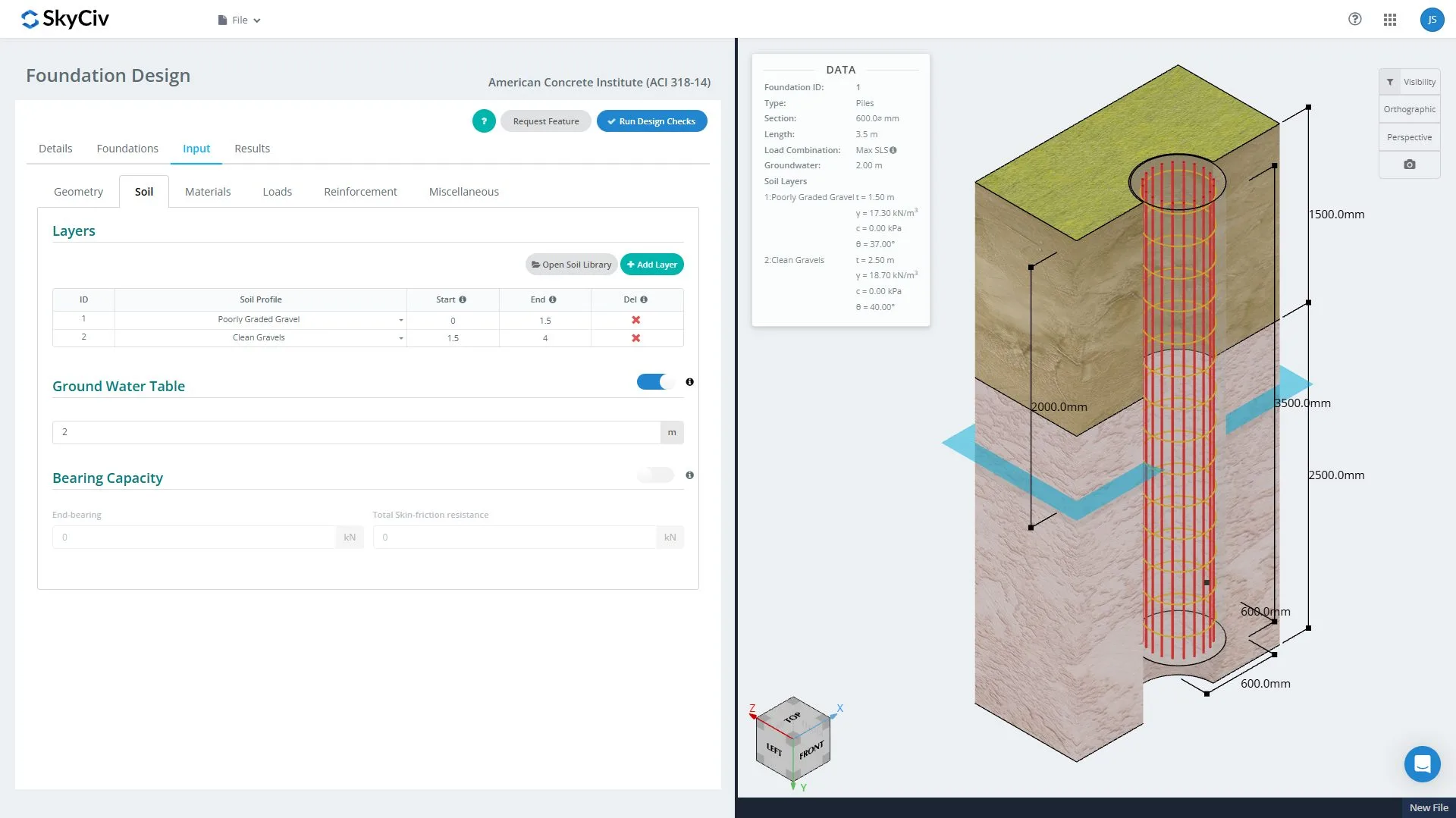
Adding, removing, or adjusting soil layers can be modified through the table on the soil configurations tab. All soil layers and properties are 3D-rendered in the right panel, which updates in real time whenever changes occur. The groundwater table option can be toggled on or off. By default, the groundwater table is off, meaning it is absent from any soil layer. End-bearing capacity and total skin-frictional resistance can be manually overwritten if they are available from the geotechnical report.
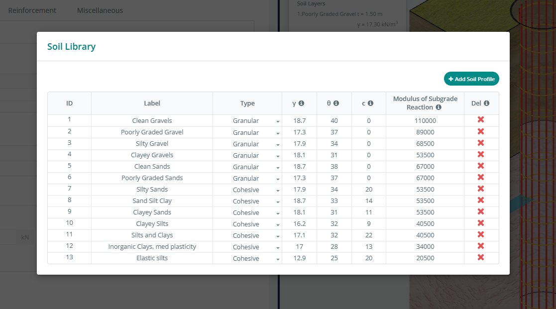
Soil properties can be accessed by clicking the “Open Soil Library” button. By default, it is loaded with typical soil properties but users can easily modily, add, and remove soil data.
- ID: Soil identification number
- Label: Assign the name of the soil property
- Type: Select either Cohesive soil or Granular (cohesionless) soil
- γ: Unit weight of the soil
- θ: Friction angle
- c: Cohesion of soil
- Modulus of Subgrade Reaction: Typical values for the Modulus of Subgrade Reaction
- Del: Deletes the soil property
3. Materials
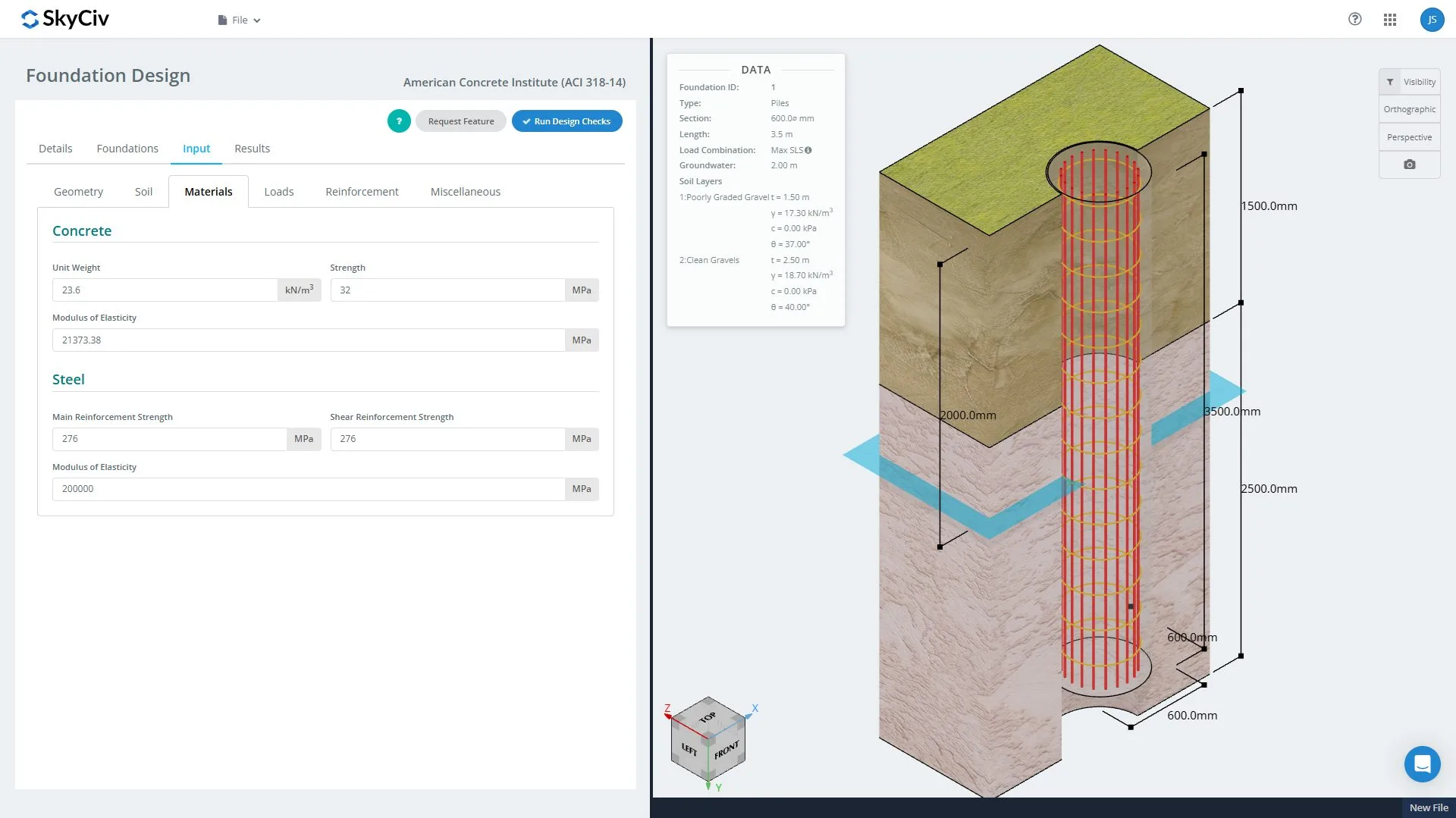
Properties for the concrete and steel reinforcements can be assigned here.
4. Loads

Loads applied on top of the pile can be assigned in this section.
- ID: Load identification number
- Load Type: Load cases (depending on the design code)
- P: Axial Force along the Y-axis (kN or kips)
- Vx: Shear force along the X-axis (kN or kips)
- Vz: Shear force along the Z-axis (kN or kips)
- Mx: Moment about the X-axis (kN-m or kip-ft)
- Mz: Moment about the Z-axis (kN-m or kip-ft)
- Delete: Deletes the load
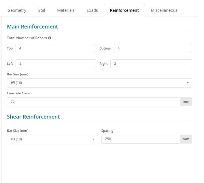
5. Reinforcement
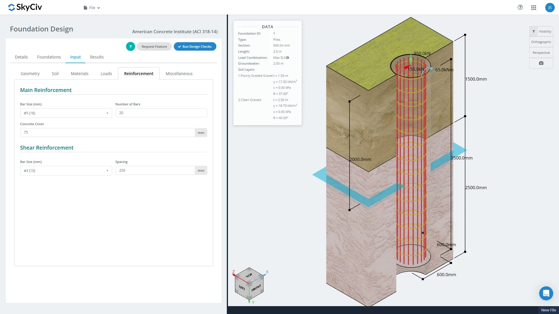
The configuration of the steel reinforcement shall be accessed through here. For round piles, only the number of bars, bar size, and concrete cover are required for the longitudinal bar layout. For rectangular piles, the number of bars on each side is required, as shown below.
6. Design Parameters
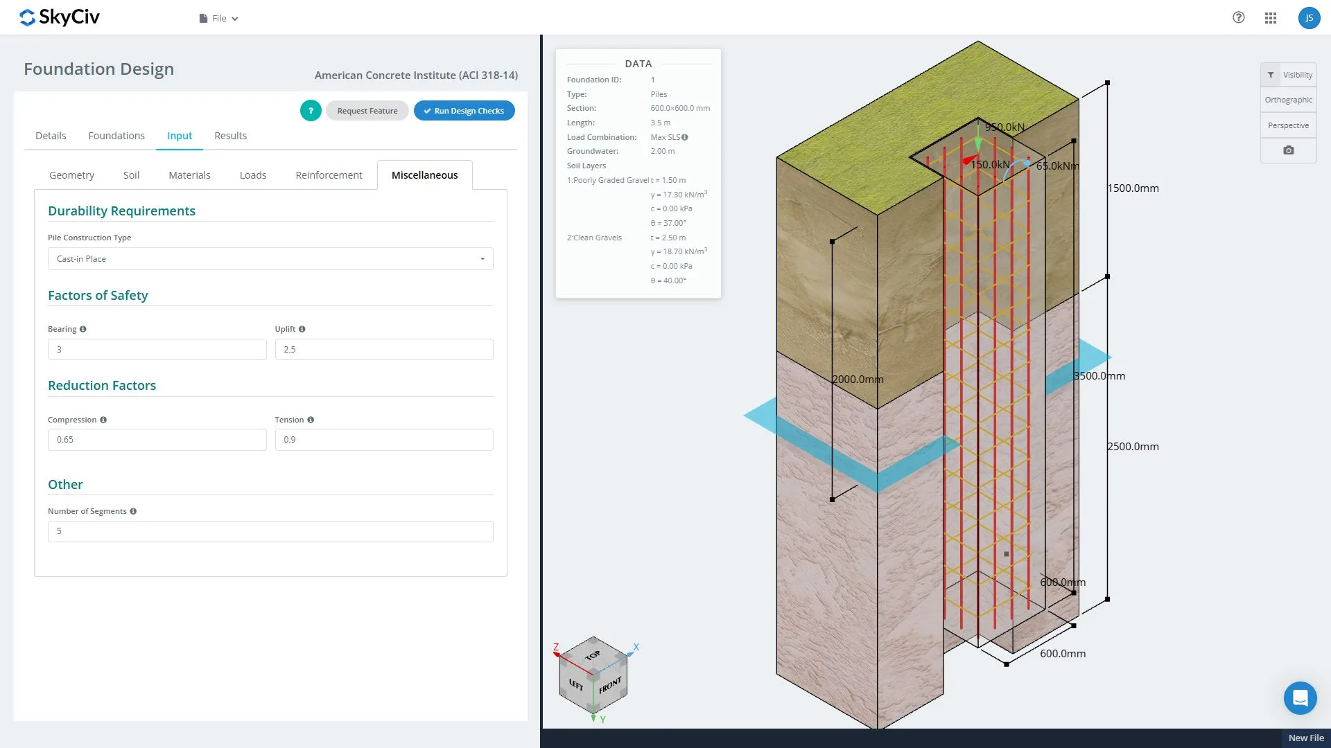
Design parameters or factors, depending on the selected design code, can be modified under the Miscellaneous tab.