Using the “View Design Wind Inputs for All Directions” in Load Generator
Site analysis is crucial in wind load calculations. By conducting this analysis, we can determine the worst wind source direction to generate the largest design wind speed and pressures.
In the SkyCiv Load Generator, this can be done by clicking the “View Design Wind Inputs for All Directions” button. However, this is only available to ASCE 7, NSCP 2015, and AS/NZS 1170 for now. Soon, we will be adding the other reference codes to aide your design process.
Try our SkyCiv Load Generator!
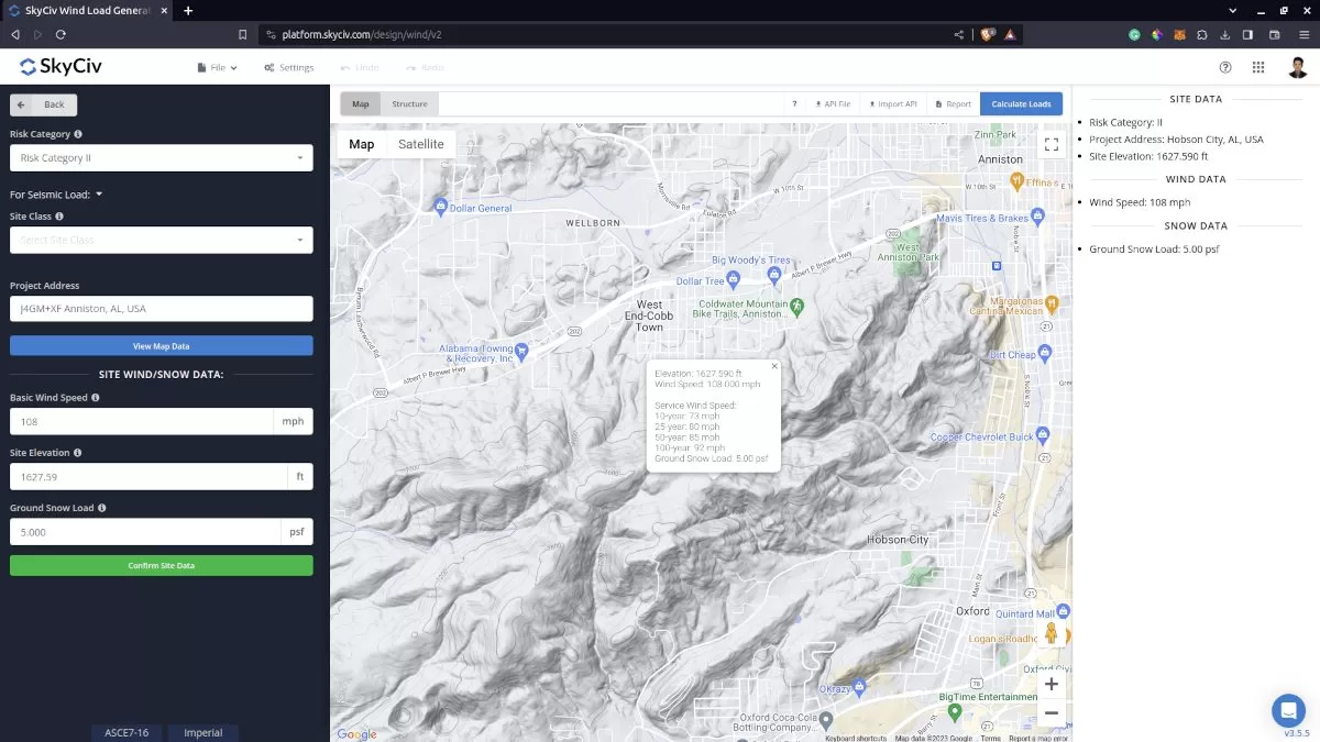
Site data for wind load calculation.
By clicking the “View Design Wind Inputs for All Directions” button above the map image, it will generate the terrain sectors for each direction. It will generate the parameters for each direction and calculate the corresponding velocity pressures. Note that the radius of the sectors is equal to 2 miles for imperial units and 2 kilometers for metric units.
For ASCE 7 and NSCP 2015, the default Exposure Category is D. This will affect the value of Velocity Pressure Exposure Coefficient \({K}_{z} \) as this depends on the Exposure Category of the upwind direction. The \({K}_{z} \) value will be calculated at 15 ft for imperial and 4.5m for metric units. This is only to compare the calculated velocity pressure differs for each direction. This factor will be then recalculated at the mean roof height, \( h \), for the design wind pressure. Moreover, the topographic factor, \({K}_{zt} \), is calculated at \( z = 0 m\) as this is the location where the maximum effect of topography can be considered.
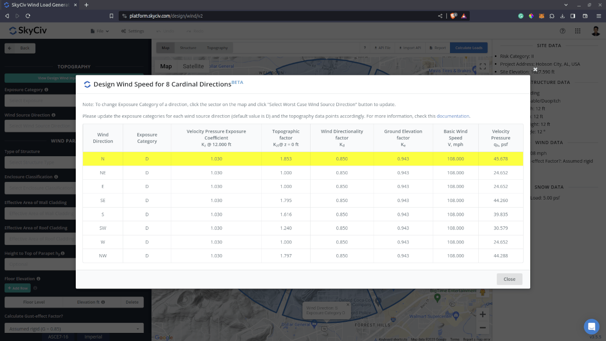
Initial values for the worst case wind source direction data.
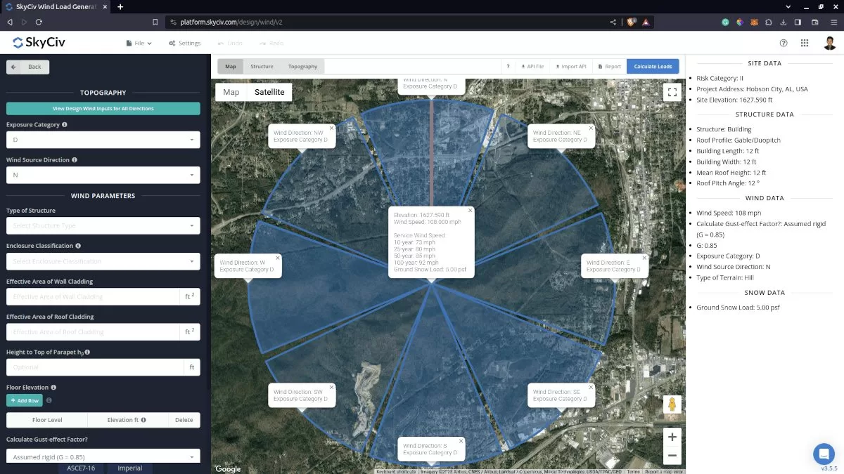
The generated editable terrain/exposure category sectors in the map.
For AS/NZS 1170, the default Terrain Category is 1. This will affect the value of Terrain/Height Multiplier, \({M}_{z} \), as this depends on the Terrain Category of the upwind direction. This \({M}_{z} \) factor is calculated at 3m height for comparison with all the other directions. This factor will be then recalculated at the mean roof height, \( h \), for the design wind pressure. Moreover, each direction has a corresponding Direction Multiplier, \({M}_{d} \), which definitely has an impact on the Design wind speed. Moreover, the topographic multiplier, \({M}_{t} \) is calculated at \(z = 0 \) as this is the location where the maximum effect can be considered.
To update each Exposure or Terrain Category, you just need to click the sectors inside the Google Map. It will change its color to indicate that the Exposure/Terrain Category is updated and will also show the information of exposure or terrain category selected. After this process, just click the “Select Worst Case Wind Source Direction” button again to update the values in the table.
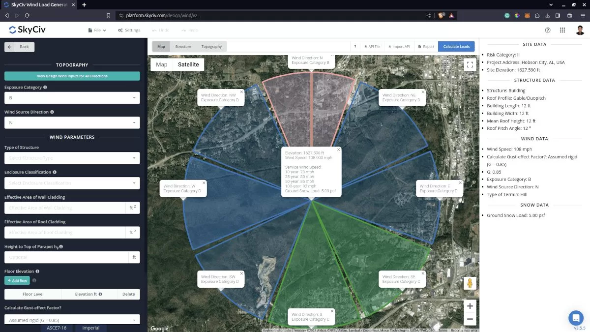
The updated terrain category for each direction.
You just need to re-click the “Select Worst Case Wind Source Direction” button again to check the changes. The maximum velocity pressure value in the table will be highlighted and can be clicked to automatically load the direction and the corresponding exposures/terrain category to the site data tab.
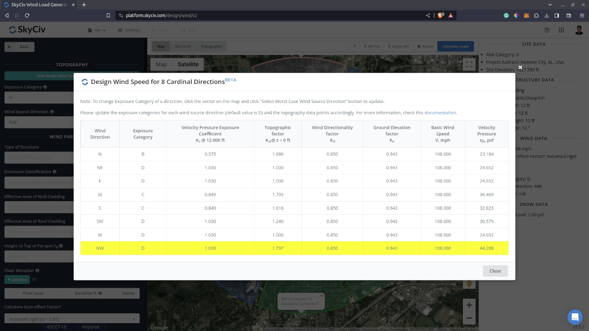
The updated parameters in determining the worst case wind source direction.
In addition, you can double-check and edit the calculated topographic factor/multiplier on the Ground Elevation chart per direction. This factor will be then saved and used in the recalculation of the Table data to determine the worst-case wind source direction.
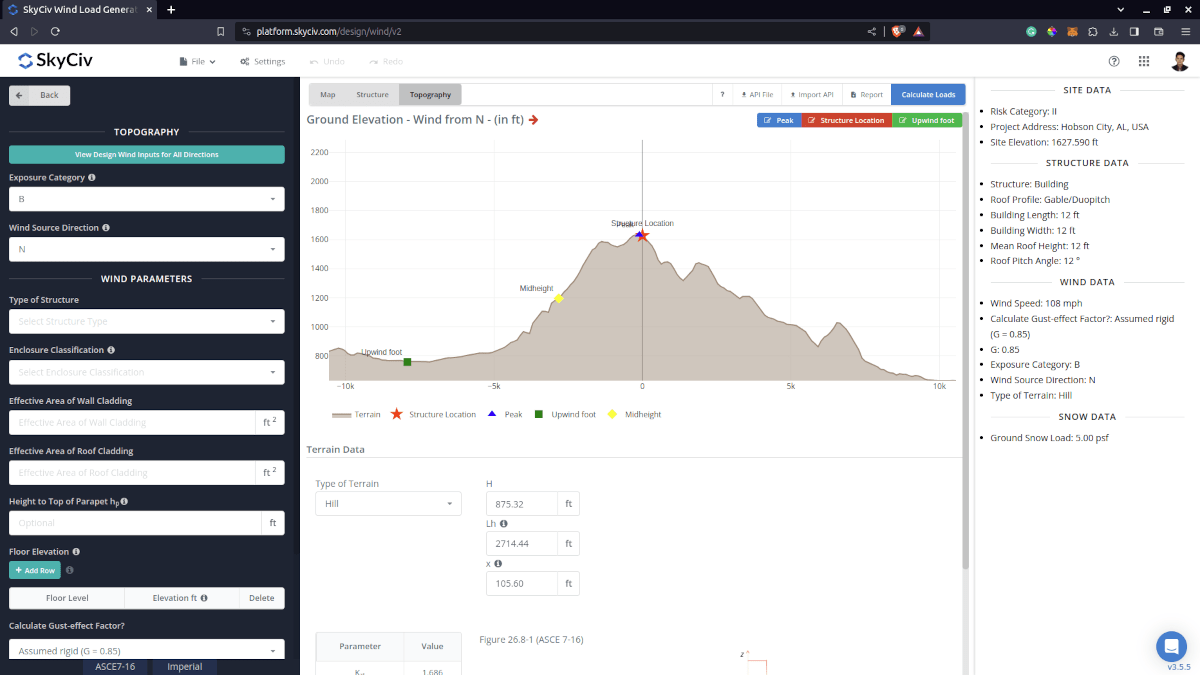
The elevation chart where you can modify the topographic factor/multiplier per wind source direction in the site analysis.
Once you’ve edited the elevation data per wind direction, you just need to re-click the “View Design Wind Inputs for All Directions” button to show you the changes in the the wind speed/pressure.
The updated velocity pressure after changing the topographic factor in the Elevation chart.
All of this process with just a few clicks! Take advantage of this feature by signing up for a Professional Account or by purchasing the standalone Load Generator module!
For additional resources, you can use these links:
- Introduction to SkyCiv Load Generator
- Effects of Topography on Wind Load
- AS/NZS 1170.2 Wind Load Calculation Example
- ASCE 7-10 Wind Load Calculation Example
- ASCE 7-10 Wind Load Calculation Example
- EN 1991-1-4 Wind Load Calculation Example
- ASCE 7-16 Wind Load Calculation Example for L-shaped Building
- IS 875-3 Wind Load Calculation Example
- Wind and Snow Loads for Ground Solar Panels – ASCE 7-16
- Wind Load Calculation for Signs – EN 1991