AISI American Iron and Steel Institute for Cold-Formed Steel Structures 2012 Edition
The American Iron and Steel Institute ( AISI S100-12 ) specification provides an integrated treatment of Allowable Strength Design (ASD), Load and Resistance Factor Design (LRFD). This is accomplished by including the appropriate resistance factors (φ) for use with LRFD and the appropriate safety factors (Ω) for use with ASD.
- Run design checks as per AISI S100 (ASD and LRFD), including checks for:
- Bending
- Flexural Buckling
- Flexural-Torsional Buckling
- Distortional Buckling Strength
- Shear Checks
- Combined Axial and Bending
- Combined Bending and Shear
- Lateral Torsional Buckling
- Supports Channel and Z-Section shapes
- Open and run directly from SkyCiv Structural 3D, SkyCiv Beam analysis software
- Control the parameters and input for each member
- Export detailed step-by-step PDF Reports
- Run the SkyCiv Designer, to determine most efficient section
Current Version Support
Sections
- Channel ( Lipped )
- Channel
- Z – Section ( Lipped )
- Z – Section
- Hat Section
Software
- SkyCiv Beam
- SkyCiv Structural 3D
- Standalone (no analysis, enter your own forces)
Note:
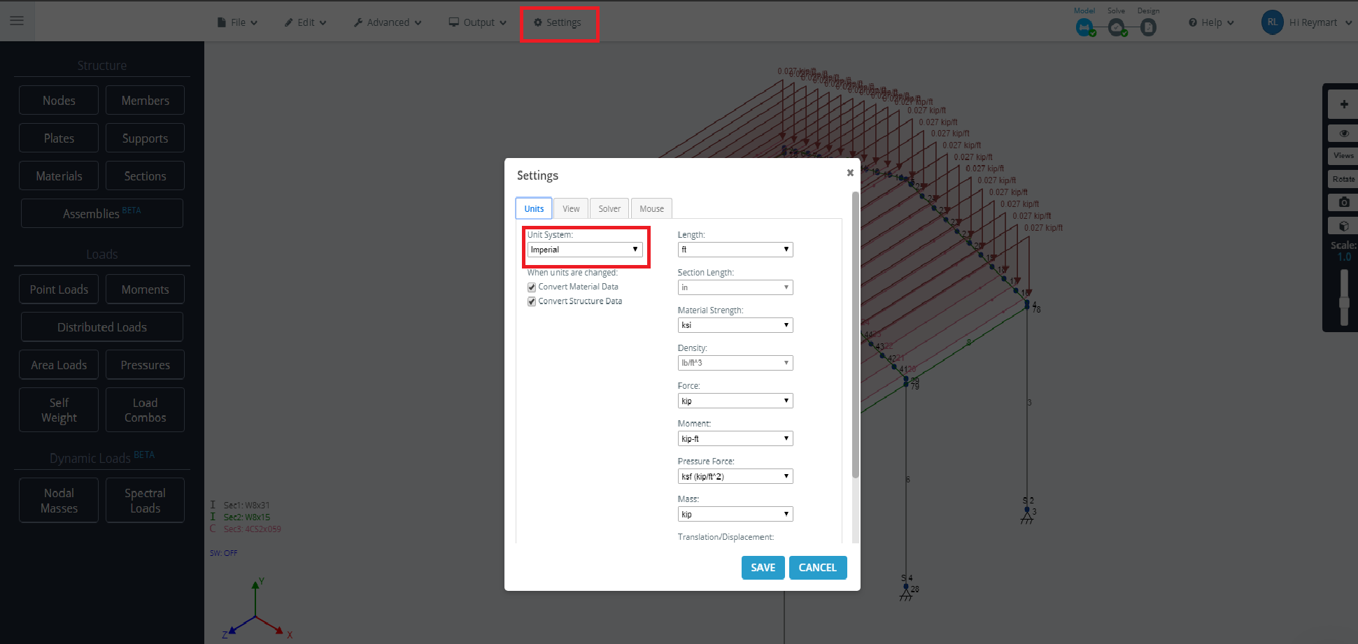
Units must be in Imperial if you wish to use this Design Module. To do that, while in the Model section go to settings and set your units to Imperial. Please see the image below:
Details
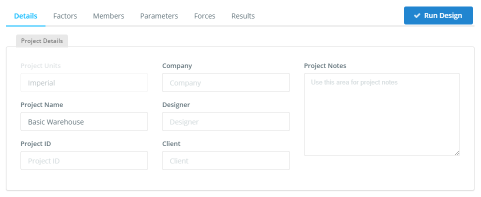
Once you have chosen either ASD or LRFD the Details tab will show up. Here you can input all the project details. They are not required to be filled unless you want them to be shown on your report later.
Factors
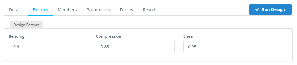
On the Factors tab, here the inputs are automatically populated by the Skyciv program. It can be modified.
Members
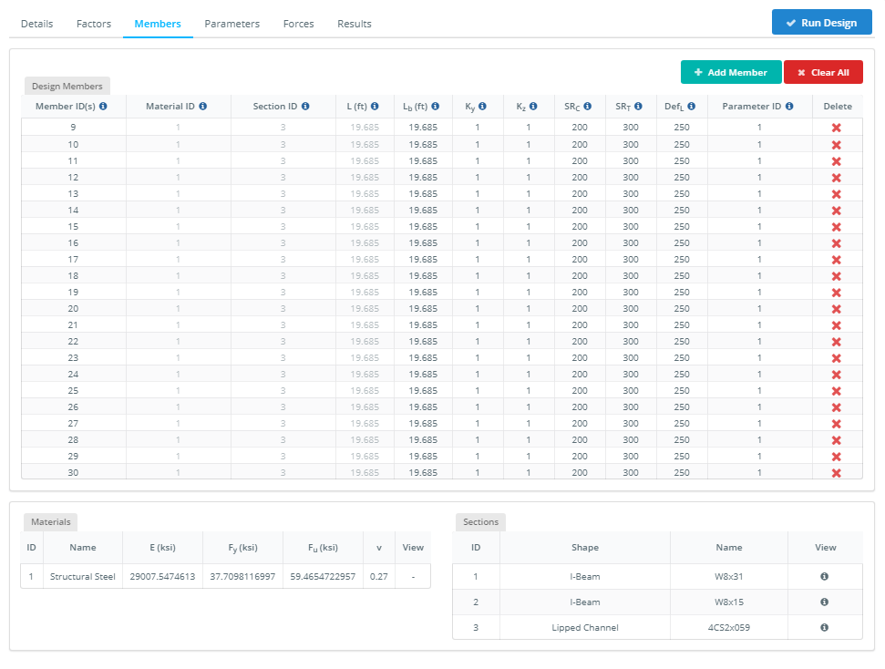
The Members tab contains all the input related to each of the members to be designed in the module. These may contain specific parameters for each design software (hover over the tooltips for more info). These can be changed at any time by changing the values in the cells.
Design Members
The Design Member table contains all the members, their materials, section IDs, length and their limit factors that have been automatically populated from the model. You can also delete certain members that you don’t want to include in the design check.
The materials and Sections (in the lower tables) are automatically populated from the model. You can hover over the icon for more information.
-
- Member ID(s) – Member(s) from your model that make up the design member.
- Material ID – The Material ID of the design member from the Material Table. It can be modified.
- Section ID – The Section ID of the design member from the Section Table below.
- L ( ft ) – The total length of the design member.
- Lb ( ft ) – Length between bracing points. It can be modified.
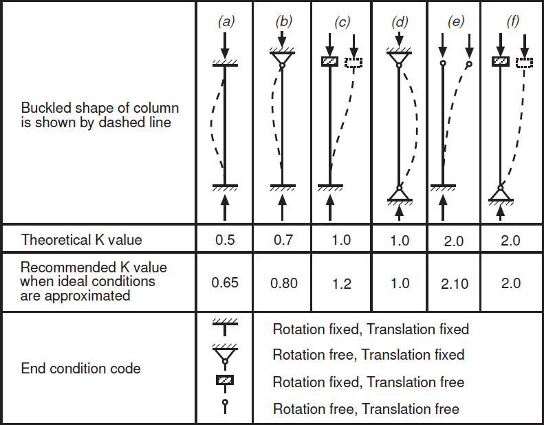
- Ky and Kz – Effective Length factors for flexural buckling about y-axis and z-axis. It is calculated automatically but it can be modified
-
- SRc – Slenderness ratio for Compression. The default value equals 200 as per AISI S100-12 (C4.1 – F). It can be modified.
- SRt – Slenderness ratio for Tension. The default value equals 300 as per AISI S100-12 (C4.1 – F). It can be modified.
- DefL – Deflection limit ratio. It can be modified.
- Parameters ID(s) – Type of Parameter to be used in the analysis of the design member.
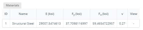
Materials
The materials table is automatically populated by the Skyciv program. Changing it would require you to go to the model section. It cannot be modified.
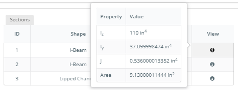
Sections
Like the Materials table. This Section table is automatically populated by the Skyciv program. It is based on the Sections you have chosen and applied to your model. In the AISI Design Module, only Cold-Formed Sections are allowed to be analyzed by the program. As it aims to provide only for Cold-Formed Sections. Hence, when you proceed with other Sections the program will not run and give you a warning message.
You can hover over the icon in the View column for more information about the cross-section properties.
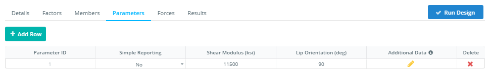
Parameters
The Parameters tab contains all the input related to each of the members to be designed in the module. The module uses these parameters for automatic calculation of Adjustment Factors. These can be changed at any time by changing the values in the cells. Here you can delete or add additional types of Parameter if you prefer several parameters to be used in your model. Every time you add a new Parameter, the table automatically gives it a unique number ID so that you would be able to determine which parameter you are going to use.
-
-
-
-
- Parameter ID(s) – The unique number of parameter registration. To be used in the Members table
-
- Simple Reporting – This parameter toggles the detailed reporting. The default value is No. Which provides a detailed reporting.
-
- Shear Modulus ( ksi ) – This parameter has the default value of 11300 ksi as per AISI S100-12. See Symbol and Definitions. It can be modified.
-
- Lip Orientation ( deg ) – This parameter has the default value of 90 degrees. It can be modified.
- Additional Data – If you wish to modify the current default parameter.
-
-
-
Parameters: Additional Data options
This Additional Data form contains all the parameters to be used for analyzing a certain design member. Here you can edit the parameters of your choice.
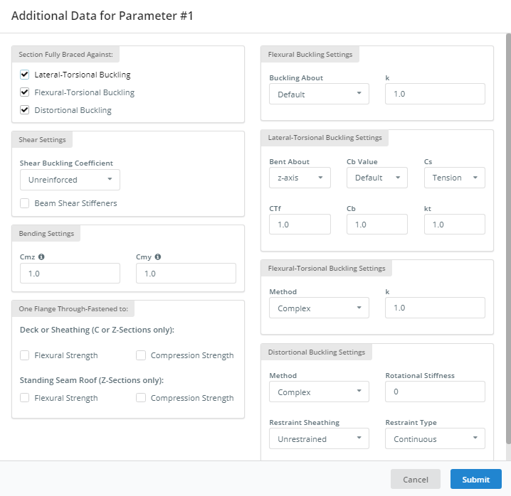
Section Fully Braced Against:
- Lateral-Torsional Buckling – Provides Lateral-Torsional Buckling result when checked. The default value is checked.
- Flexural-Torsional Buckling – Provides Flexural-Torsional Buckling result when checked. The default value is checked.
- Distortional Buckling – Provides Distorsional Buckling result when checked. The default value is checked.
Bending Settings:
- Cmz – Coefficient of unequal end at Z axis. The default value is 1. It can be modified.
- Cmy – Coefficient of unequal end at Y axis. The default value is 1. It can be modified.
Shear Settings:
This frame contains the Shear Buckling Coefficient (kv) as per C3.2.1
- Shear Buckling Coefficient ( kv ) – Unreinforced, sets the kv = 5.34. And Reinforced, kv will be calculated as per AISI S100-12 ( C3.2.1-6/7 ).
- Shear Panel Length ( in ) – This option is applicable only if Shear Buckling Coefficient is set to Reinforced.
- Beam Shear Stiffiner – This option affects the result and formula to be used in the Combined Bending and Shear as per AISI S100-12 ( C3.3 ). The default value is checked.
One Flange Through-Fastened:
- Deck or Sheathing ( D6.1.1 ).
- Flexural Strength – Once this toggled. Flexural Strength will be considered as per AISI S100-12 ( D6.1.1 ).
- Reduction Factor ( Rf ) – Reduction factor that is needed for Flexural Strength as per AISI S100-12 ( Table D6.1.1-1 ). The default value is 1. It can be modified.
- Compression Strength – Once this toggled. Compression Strength will be considered as per AISI S100-12 ( D6.1.3 ).
- Fastener Distance ( in ) – Reduction factor that is needed for Flexural Strength as per AISI S100-12 ( Figure D6.1.3, Definition of x ). The default value is 1. It can be modified.
- Standing Seam Roof ( D6.1.2/4 ).
- Flexural Strength – Once this toggled. Flexural Strength will be considered as per AISI S100-12 ( D6.1.2 ).
- Reduction Factor ( Rf ) – Reduction factor that is needed for Flexural Strength as per AISI S100-12 ( Table D6.1.1-1 ). The default value is 1. It can be modified.
- Compression Strength – Once this toggled. Compression Strength will be considered as per AISI S100-12 ( D6.1.4 ).
- Compression Factor ( Rc ) – Default value is 1. It can be modified.
Flexural Buckling Settings:
- Buckling About -Choose either Z or Y-Axis. It is set to Default ( Z-axis). It can be modified.
Lateral-Torsional Buckling Settings:
- Bent About – Choose either Z or Y-Axis. The default value is Z-axis. It can be modified.
- End Moment Coefficient ( CTF ) – The default value is 1. It can be modified.
- Bending Moment Coefficient ( Cb Value / Cb ) – Choose either Default or Calculated. The Default will consider Cb having a value of 1. While Calculated will perform the formula as per AISI S100-12 ( C3.1.2.1-6 ).It can be modified.
- Coefficient of lateral-torsional buckling ( Cs ) – Choose either Tension or Compression. Choosing Tension will set the Cs value to -1. While Compression will set the Cs value to 1.
- Effective length factors for twisting ( Kt ) – The default value is set to 1. It can be modified. AISI S100-12 ( C3.1.2.1-9 ).
Flexural-Torsional Buckling Settings:
- Method – Choose either Complex or Simplified. The Complex will calculate the result as per AISI S100-12 ( C4.1.2-1 ). While Simplified will consider using as per AISI S100-12 ( C4.1.2-2 ).
Distorsional Buckling Settings:
- Method – Choose either Complex or Simplified. The Complex will calculate the result as per AISI S100-12 ( C3.1.4-6 ). While Simplified will consider using as per AISI S100-12 (
C-C3.1.4-1).
- Rotational Stiffness ( kφ – kip-in./rad./in ) – The default value is set to 0. It can be modified.
- Restraint Sheathing – Choose either Unrestraint or Restraint. Choosing Unrestraint will ignore the Rotational Stiffness. While Restraint will require you to input the Rotational Stiffness ( kφ – kip-in./rad./in ).
- Restraint Type– Choose either Continuous or Irregular. Choosing Continuous will set Lm = Lcr. Choosing Irregular will calculate the Lm based on the maximum and minimum bending moment.
Forces
Internal member forces are automatically imported from the structural analysis, this includes load combinations. The software will display each of the forces as per the selected load combination. The software will design check based on the worst case for each member and load combination.
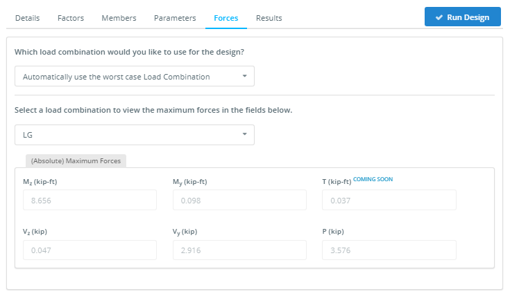
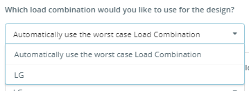
By default, the module uses the worst-case load combination, but you can choose one of them for design.
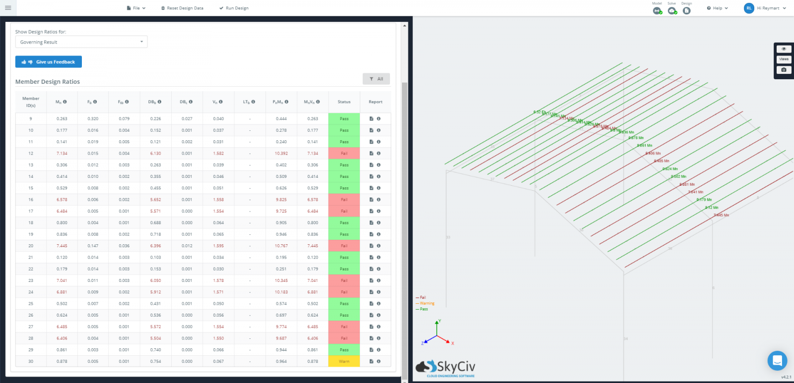
Results
There are three ways to review the results of your design check:
-
-
-
- Tabulated Results – on the left side, in the status column. It shows a Green color having the status of Pass. And Red color having the status of Fail. Whilst Yellow color having the status of Warn.
- Graphical Results – on the right side, the structure will display the green, red, and yellow ( if any ) coloring of each member as well as the highest capacity ratio of all the results. The green color indicates that the capacity ratio of the member is lesser than 1. And the red color indicates that the capacity ratio of the member is greater than 1. Whilst the yellow color indicates that the capacity ratio of the member has reached 0.95 or is nearer to 1.
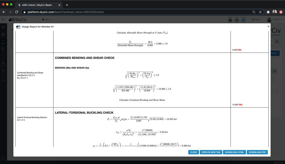
- Reporting – You can export a PDF summary report of the design checks any time.
-
-
As with all SkyCiv design software, the calculations also come with open and detailed PDF reporting, showing the step by step calculations:
Related tutorial
Learn more on how to design a cold-formed steel structure in the SkyCiv Structural 3D with our Cold Formed Steel Design Example tutorial that covers modeling, analysis, and designing of the structure. In that tutorial, we’ll show step-by-step on how to create nodes, members, sections, materials, supports, loads, and load combinations.