A fully worked example of NBCC 2015 snow load calculations
Accumulation of snow on structures can be very hazardous to roof members or other exposed structural elements. The National Building Code of Canada (2015) Division B – Section 4.1.6 provides a detailed calculation of snow loads and the associated rain loads. Using this guideline, we will demonstrate how to calculate the snow loads using an example Structural 3D (S3D) warehouse model, as shown below:
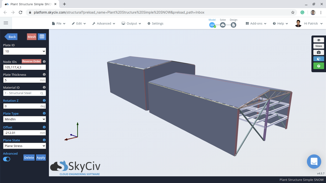
Figure 1: Example S3D warehouse model
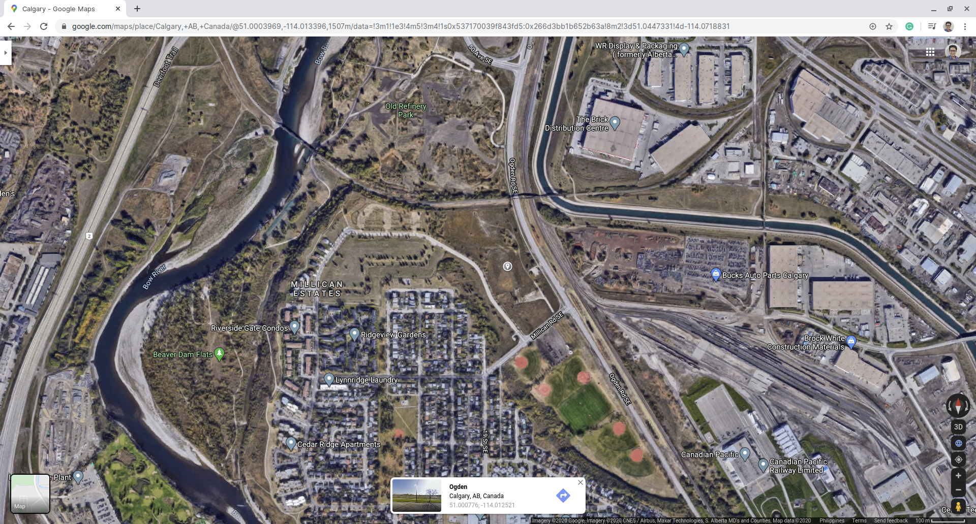
Figure 2: Example site location using Google Maps (for illustration only).
Table 1: Building data needed for our snow load calculation.
| Location | Ogden, Calgary, Alberta (for illustration only) |
| Occupancy | Warehouse or Storage of materials |
| Dimensions | 19.508 m x 31.70 m for each structure Eave height of smaller building 9.144 m Apex height of smaller building 11.941 m Difference of upper and lower roof is 3.50 m Roof pitch angle 16° |
| Additional Details | Roof has a slippery surface Gap between structures is 2.30 m |
From Table 1, the specified snow load, \(S\), can be calculated using the formula:
\(S = {I}_{s}[{S}_{s}{C}_{b}{C}_{w}{C}_{s}{C}_{a} +{S}_{r}]\) (1)
Where:
\({I}_{s}\) = importance factor for snow load, Table 4.1.6.2-A
\({S}_{s}\) = 1-in-50 year ground snow load, kPa, Subsection 1.1.3
\({C}_{b}\) = basic roof snow load factor, 4.1.6.2 (2)
\({C}_{w}\) = wind exposure factor based, 4.1.6.2 (3) and (4)
\({C}_{s}\) = slope factor, 4.1.6.2 (5), (6), and (7)
\({C}_{a}\) = accumulation factor, 4.1.6.2 (8)
\({S}_{r}\) = 1-in-50 year associated rain load, kPa, Subsection 1.1.3, but not greater than \({S}_{s}{C}_{b}{C}_{w}{C}_{s}{C}_{a}\)
Each parameter will be examined individually in the following sections. The following snow load cases will be calculated: balanced and unbalanced snow load on each roof (wind normal to ridge), as well as the drift generated on the lower roof considering accumulation from sliding.
Importance Factor, \({I}_{s}\)
The first thing that is determined is the importance factor, \({I}_{s}\), which is found using Table 4.1.6.2-A as referenced. Since the structure is a storage building that has a low direct impact on human life in the event of failure, the importance category is Low. Moreover, the calculation will be in the Ultimate Limit State (ULS). So from Table 4.1.6.2-A, \({I}_{s}\) is equal to 0.80.
| Importance Category | Importance Factor, \({I}_{s}\) | |
|---|---|---|
| ULS | SLS | |
| Low | 0.8 | 0.9 |
| Normal | 1.0 | 0.9 |
| High | 1.15 | 0.9 |
| Post-disaster | 1.25 | 0.9 |
Ground Snow Load, \({S}_{s}\), and Associated Rain Load, \(({S}_{r})\)
The ground snow load, \({S}_{s}\), and associated rain load, \(({S}_{r})\), values are tabulated in Appendix C, Division B of NBCC 2015 depending on location and province. For this example, the corresponding \({S}_{s}\) and \(({S}_{r})\) in Calgary Alberta is equal to 1.10 kPa and 0.1 kPa, respectively.
Having a hard time searching for the ground snow and associated rain load for NBCC 2015? Try the SkyCiv Free Load Generator Tool to speed up your search and get the corresponding \({S}_{s}\) and \({S}_{r}\) based on the location of your structure.
Wind Exposure Factor, \({C}_{w}\)
For the wind exposure factor, \({C}_{w}\), it shall be permitted to be equal to 1.0 based on 4.1.6.2 (3). This factor can still be reduced as long as the conditions in 4.1.6.2 (4) is satisfied. For this example, \({C}_{w}\) shall be equal to 1.0 since the location is not an open terrain that fully exposes the structure to the wind.
Basic Roof Snow Load Factor, \({C}_{b}\)
The basic roof snow load factor, \({C}_{b}\), can be calculated using the following formulas, as referenced in 4.1.6.2 (2):
\({C}_{b} = 0.8\) (2) for \({l}_{c} ≤ (70/{{C}_{w}}^{2})\) and
\({C}_{b} = (1/{C}_{w}) [1 – (1 – 0.8{C}_{w})exp(-0.01({l}_{c}{{C}_{w}}^{2} – 70))] \) (3) for \({l}_{c} > (70/{{C}_{w}}^{2})\)
Where:
\({l}_{c}\) = characteristic length of the upper or lower roof defined as: \(2w -{w}^{2}/l\)
\(l\) = larger plan dimension of the roof
\(w\) = smaller plan dimension of the roof
For this example,\(l\) and \(w\) is equal to 31.7 m and 19.51 m, respectively, hence, \({l}_{c}\) is equal to 27.01. Since \({l}_{c}\) is less than \((70/{1.0}^{2})\), the basic roof snow load factor, \({C}_{b}\), is equal to 0.8.
Slope Factor, \({C}_{s}\)
The calculation of slope factor is \({C}_{s}\) detailed in 4.1.6.2 (5), (6), and (7) is shown below.
For unobstructed slippery roof:
\({C}_{s} = 1.0\) for \(α ≤ 15°\)
\({C}_{s} = 0\) for \(α > 60°\)
\({C}_{s} = (60° – α)/45°\) for \(15° < α ≤ 60°\)
For other cases:
\({C}_{s} = 1.0\) for \(α ≤ 30°\)
\({C}_{s} = 0\) for \(α > 70°\)
\({C}_{s} = (70° – α)/40°\) for \(30° < α ≤ 70°\)
Specific Weight of Snow, \(γ\)
The specific weight of snow is specified in 4.1.6.13 and shall be taken as:
\(γ = 0.43{S}_{s} + 2.2 kN/{m}^{3} ≤ 4.0kN/{m}^{3}\) (4)
For this example, \(γ\) is equal to \(2.673 kN/{m}^{3}\).
Accumulation Factor, \({C}_{a}\)
Accumulation factor, \({C}_{a}\), is calculated depending on the load case being considered as detailed in 4.1.6.2 (8). This value will be calculated in detail per each case.
Specified Snow Load, \(S\)
In this section, the Specified Snow Load, \(S\), will be calculated for the balanced and drifted cases.
Balanced/Undrifted Case
For the balanced/undrifted case, the accumulation factor \({C}_{a}\) is equal to 1.0. Moreover, since the roof pitch angle \(α\) is \(16°\) and the roof surface is assumed to be unobstructed slippery, the slope factor, \({C}_{s}\), for our example is equal to 0.978. Using equation (1), the specified snow load, \(S\), for balanced/undrifted case is:
\(S = 0.8((1.10)(0.8)(1.0)(0.978)(1.0) +0.1)\) = 0.769 kPa
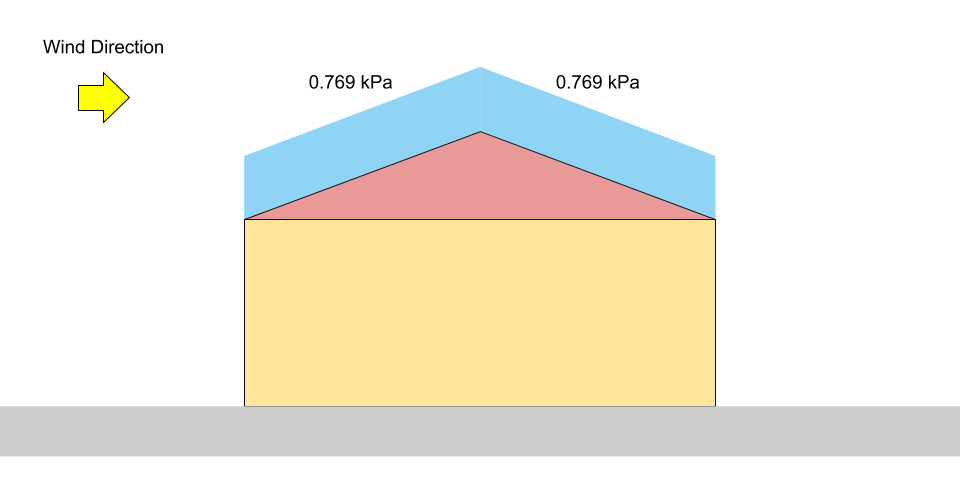
Figure 3: Load diagram for balanced snow load on a gable roof.
Unbalanced/Drifted Case
Wind Acting Normal to Ridge
Since the structures have gable roofs, the unbalanced snow load (wind acting normal to the ridge) accumulation factor \({C}_{a}\) is found using 4.1.6.9:
\({C}_{a, upwind} = 0\)
\({C}_{a, downwind} = 0.25 +α/20\) for \(15° ≤ α ≤ 20°\)
\({C}_{a, downwind} = 1.25\) for \(20° < α ≤ 90°\)
Because both structures have roof pitch angle equal to 16°, the accumulation factors \({C}_{a, upwind}\) and \({C}_{a, downwind}\) are equal to 0 and 1.05, respectively. Moreover, since the roof pitch angle \(α\) is \(16°\) and the roof surface is assumed to be unobstructed slippery, the slope factor, \({C}_{s}\), for our example is equal to 0.978.
In the unbalanced/drifted case normal to the ridge, \({C}_{a}\) shall be computed based on 4.1.6.9 for a gable roof case. From the calculation above, \({C}_{a, upwind} = 0\) and \({C}_{a, downwind} = 1.05\). Hence, the specified snow loads for each side are:
\({S}_{upwind} = 0.8((1.10)(0.8)(1.0)(0.978)(0) +0.1)\) = 0.08 kPa = \({p}_{1}\)
\({S}_{downwind} = 0.8((1.10)(0.8)(1.0)(0.978)(1.05) +0.1)\) = 0.803 kPa = \({p}_{2}\)
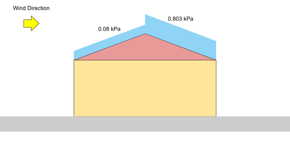
Figure 4: Load diagram for unbalanced snow load on a gable roof (not to scale).
Wind Acting Parallel to Ridge – Case I – Wind From Upper to Lower Roof
When wind is acting parallel to the ridge, a snowdrift will most likely be developed on the lower roof. In order to determine the accumulation factor \({C}_{a}\), the following formulas from 4.1.6.2 (8) are used:
\({C}_{a} ={C}_{a0} – ({C}_{a0} – 1)(x/{x}_{d})\) for \(0 ≤ x ≤ {x}_{d}\)
\({C}_{a} = 1.0\) for \(x > {x}_{d}\)
Where:
\({C}_{a0}\) = peak value of \({C}_{a0}\) at x = 0
\(x\) = distance from roof step
\({x}_{d}\) = length of drift as shown in Figure 3 below
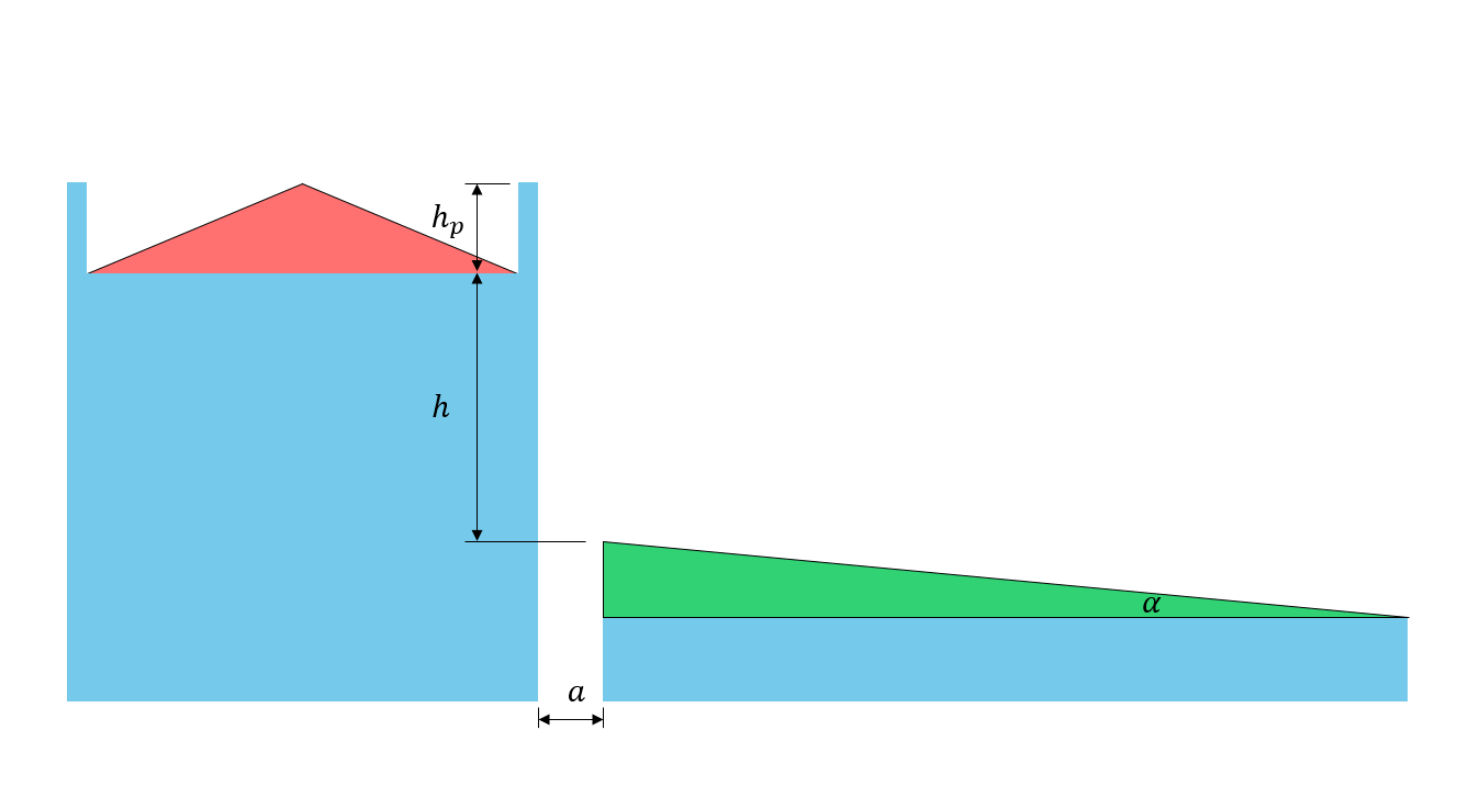
Figure 5: Illustration of roof dimension parameters
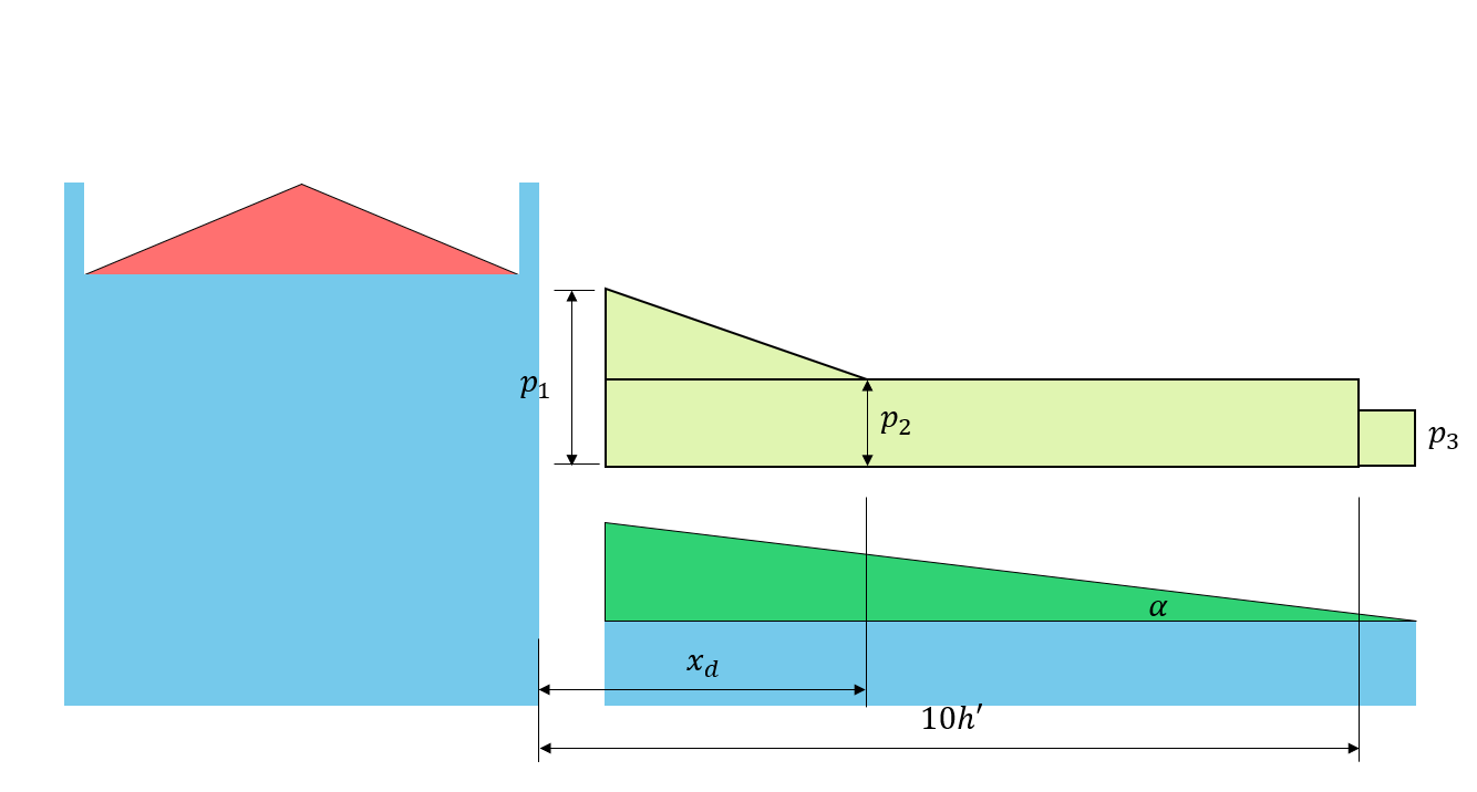
Figure 6: Corresponding drift load on the lower roof based on Figure 4.1.6.5-A.
\({C}_{a0}\) and \({x}_{d}\) can be calculated using the following formulas:
\({C}_{a0} = \frac{βγh}{{C}_{b}{S}_{s}}\) or \({C}_{a0} = \frac{F}{{C}_{b}}\) (5), whichever is lesser
\({x}_{d} = 5 \frac{{C}_{b}{S}_{s}}{γ}({C}_{a0} – 1)\) (6)
\(F = 0.35β\sqrt{\frac{γ({l}_{cs} – 5{{h}_{p}}^{‘})}{{S}_{s}}} +{C}_{b}\) but \(F ≤ 5\) for \({C}_{ws} = 1.0\) (7)
\({h}^{‘} = h – \frac{{C}_{b}{C}_{w}{S}_{s}}{γ}\) (8)
\({{h}_{p}}^{‘} ={h}_{p} – \frac{0.8{S}_{s}}{γ}\) but \(0 ≤ {{h}_{p}}^{‘} ≤ \frac{{l}_{cs}}{5}\) (9)
Where:
\({h}_{p}\) = height of parapet on upper roof (0 in this case since there is no parapet)
\(h\) = difference in height between upper and lower roof level
\({C}_{ws}\) = value of \({C}_{w}\) applicable to the source of drifting
\({l}_{cs}\) = characteristic length of the source area defined as: \(2{w}_{s} -{{w}_{s}}^{2}/{l}_{s}\)
\({l}_{s}\) = larger plan dimension of the source area as shown in Figure 7 and 8, shown below
\({w}_{s}\) = smaller plan dimension of the source area as shown in Figure 7 and 8, shown below
\(β\) = 1.0 for Case I, and 0.67 for Case II and III.
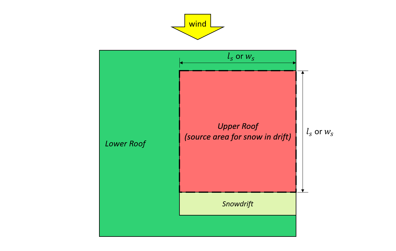
Figure 7: Case I – snowdrift formed from the wind coming from the upper roof based on Figure 4.1.6.5-B.
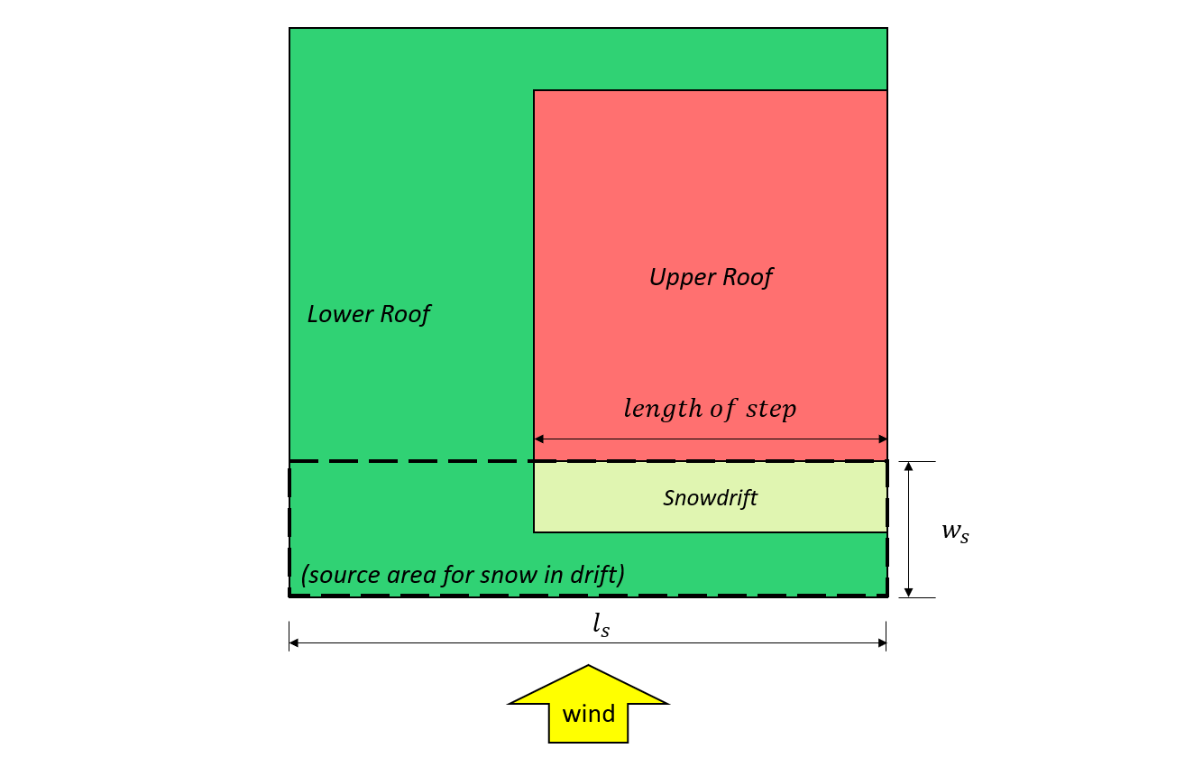
Figure 8: Case II – snowdrift formed from the wind coming from the lower roof based on Figure 4.1.6.5-B.
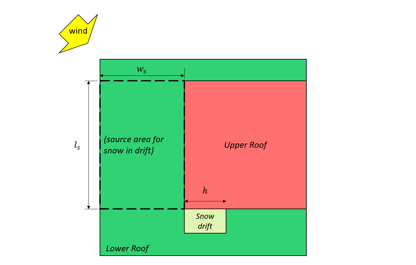
Figure 7: Case III – partial snowdrift formed from the wind coming from the lower roof based on Figure 4.1.6.5-B.
For this example, Cases I and II will be considered.
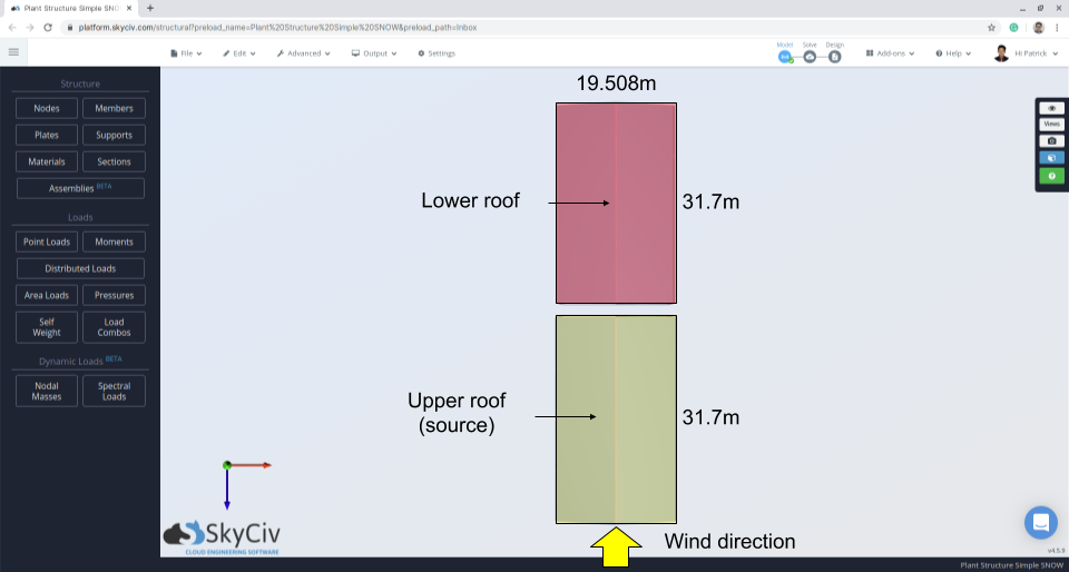
Figure 10: Structure plan indicating wind direction and source area.
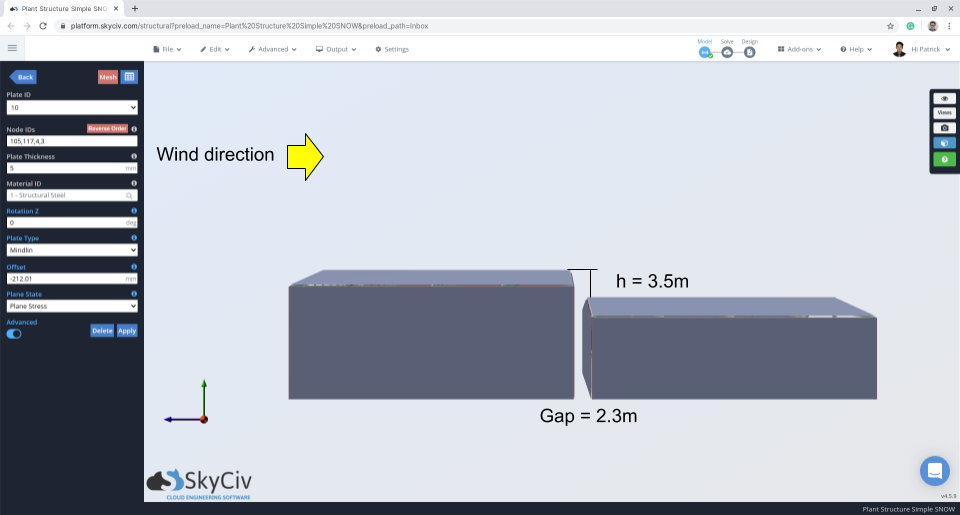
Figure 11: Elevation view indicating gap and difference of upper and lower roof.
For the unbalanced/drifted case parallel to the ridge, \({C}_{a}\) shall be calculated for Case I and Case II based on 4.1.6.5 for the multi-level roof. For Case I, these following parameters should first be calculated using the various equations previously mentioned in this example:
\(β = 1.0\)
\({h}^{‘} = (3.5) – \frac{(0.8)(1.0)(1.10)}{(2.673)} = 3.17 m\)
\({h}_{p} = 0\)
\({{h}_{p}}^{‘} =0\)
\({l}_{cs} = 2(19.507) -{(19.507)}^{2}/(31.7) = 27.01 m\)
\(F = 0.35(1.0)\sqrt{\frac{(2.673)((27.01) – 5(0))}{(1.10)}} +(0.8) = 3.636\)
\({C}_{a0} = \frac{(1.0)(2.673)(3.5)}{(0.8)(1.10)} = 10.631\) or \({C}_{a0} = \frac{3.66}{0.8} = 4.544\)
\({C}_{a0} = 4.544\)
\({x}_{d} = 5 \frac{(0.8)(1.10)}{2.673}(4.544 – 1) = 5.835 m\)
From these parameters, the accumulation factor, \({C}_{a}\), can be calculated by substituting the value of \({C}_{a0}\) at each \(x\) distance. Take note that we need to calculate \({C}_{a}\) at \(x = a\) where \(a\) is the gap between the roof since the roof gap is less than 5 m as specified in 4.1.6.6.
at \(x = 0\): \({C}_{a} =4.544 – (4.544 – 1)(0/5.835) = 4.544\)
at \(x = a\): \({C}_{a} =4.544 – (4.544 – 1)(2.3/5.835) = 3.147\)
at \(x = {x}_{d}\): \({C}_{a} =1.0\)
at \(x = 10{h}^{‘}\): \({C}_{a} =1.0\)
Since the roof angle for this case is equal to 0° in reference this section, \({C}_{s} = 1.0\). Moreover, when finding the specified snow load on the upper roof, the accumulation factor, \({C}_{a}\), and slope factor, \({C}_{s}\), are both equal to 1.0. Hence, the magnitude of the specified snow loads at each location are:
at \(x = 0\): \(S =0.8((1.10)(0.8)(1.0)(1.0)(4.544) +0.1) = 3.279 kPa\)
at \(x = a\): \(S =0.8((1.10)(0.8)(1.0)(1.0)(3.147) +0.1) = 2.295 kPa = {p}_{1}\)
at \(x = {x}_{d}\): \(S =0.8((1.10)(0.8)(1.0)(1.0)(1.0) +0.1) = 0.784 kPa ={p}_{2} = {p}_{3}\)
at upper roof level: \(S =0.8((1.10)(0.8)(1.0)(1.0)(1.0) +0.1) = 0.784 kPa\)
Wind Acting Parallel to Ridge – Case II – Wind From Lower to Upper Roof
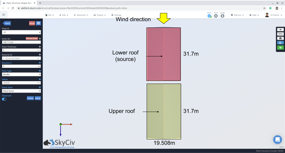
Figure 12: Structure plan indicating wind direction and source area – wind from lower roof to upper.
For Case II, the calculation is similar to Case I but has a different \(β = 0.67\):
\(β = 0.67\)
\({h}^{‘} = (3.5) – \frac{(0.8)(1.0)(1.10)}{(2.673)} = 3.17 m\)
\({h}_{p} = 0\)
\({{h}_{p}}^{‘} =0\)
\({l}_{cs} = 2(19.507) -{(19.507)}^{2}/(31.7) = 27.01 m\)
\(F = 0.35(0.67)\sqrt{\frac{(2.673)((27.01) – 5(0))}{(1.10)}} +(0.8) = 2.70\)
\({C}_{a0} = \frac{(1.0)(2.673)(3.5)}{(0.8)(1.10)} = 10.631\) or \({C}_{a0} = \frac{2.70}{0.8} = 3.375\)
\({C}_{a0} = 3.375\)
\({x}_{d} = 5 \frac{(0.8)(1.10)}{2.673}(3.375 – 1) = 3.909 m\)
at \(x = 0\): \({C}_{a} =3.375 – (3.375 – 1)(0/3.909) = 3.375\)
at \(x = a\): \({C}_{a} =3.375 – (3.375 – 1)(2.3/3.909) = 1.978\)
at \(x = {x}_{d}\): \({C}_{a} =1.0\)
at \(x = 10{h}^{‘}\): \({C}_{a} =1.0\)
at \(x = 0\): \(S =0.8((1.10)(0.8)(1.0)(1.0)(3.375) +0.1) = 2.456 kPa\)
at \(x = a\): \(S =0.8((1.10)(0.8)(1.0)(1.0)(1.978) +0.1) = 1.473 kPa = {p}_{1}\)
at \(x = {x}_{d}\): \(S =0.8((1.10)(0.8)(1.0)(1.0)(1.0) +0.1) = 0.784 kPa = {p}_{2} = {p}_{3}\)
at upper roof level: \(S =0.8((1.10)(0.8)(1.0)(1.0)(1.0) +0.1) = 0.784 kPa\)
For illustration, the corresponding \({p}_{1}\), \({p}_{2}\), and \({p}_{3}\) are shown in Figures 13 and 14 below for both Cases I and II, respectively.
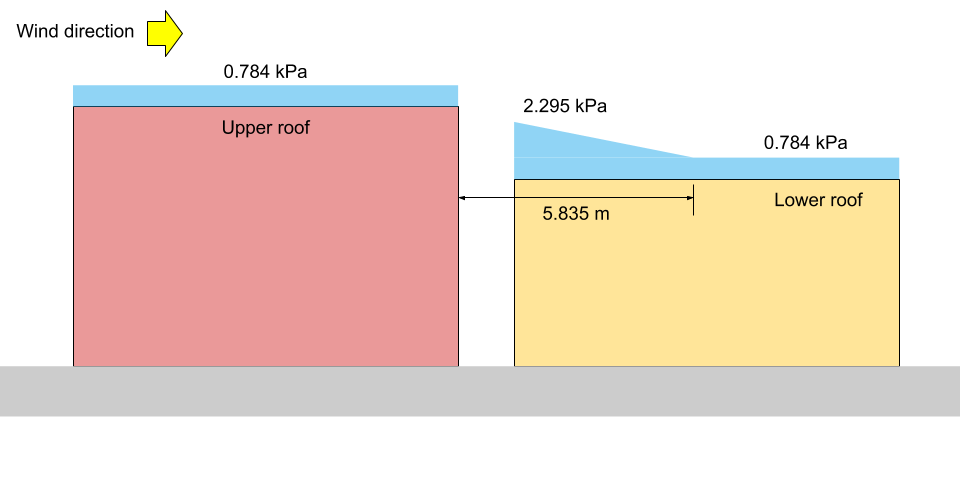
Figure 13: Snow load illustration for Case I (not to scale).
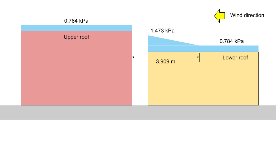
Figure 14: Snow load illustration for Case II (not to scale).
Complete these calculations automatically in minutes
That was a long calculation, what can you do as an engineer to speed up this process for your future projects? Recently SkyCiv has released and automated Snow Load Generator as a part of the SkyCiv Load Generator, which can also generate Wind Loads. To find the snow loads of the shown example, it just takes a few clicks using the tool:
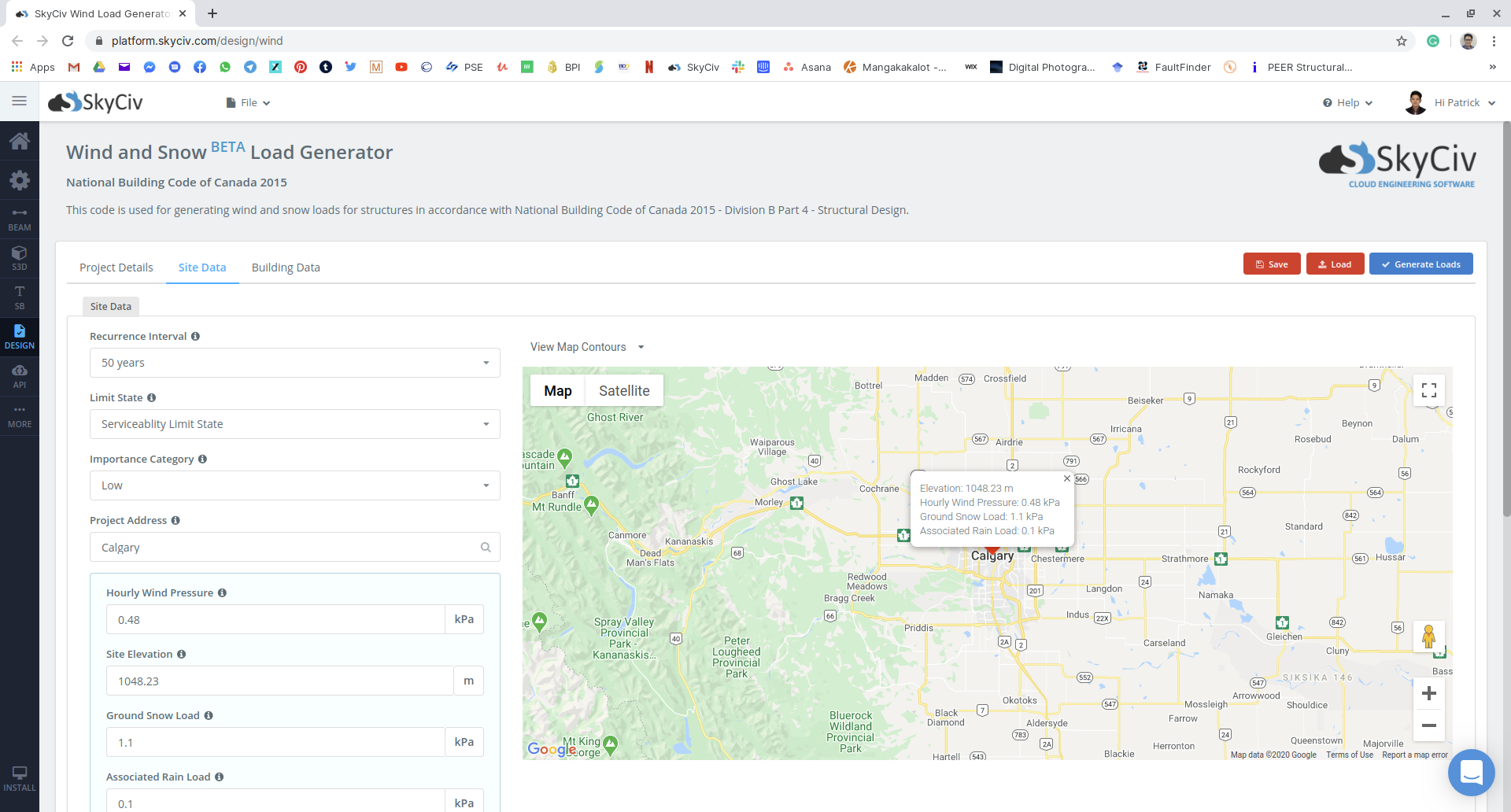
Figure 15: Site data input on SkyCiv Load Generator module using our example.
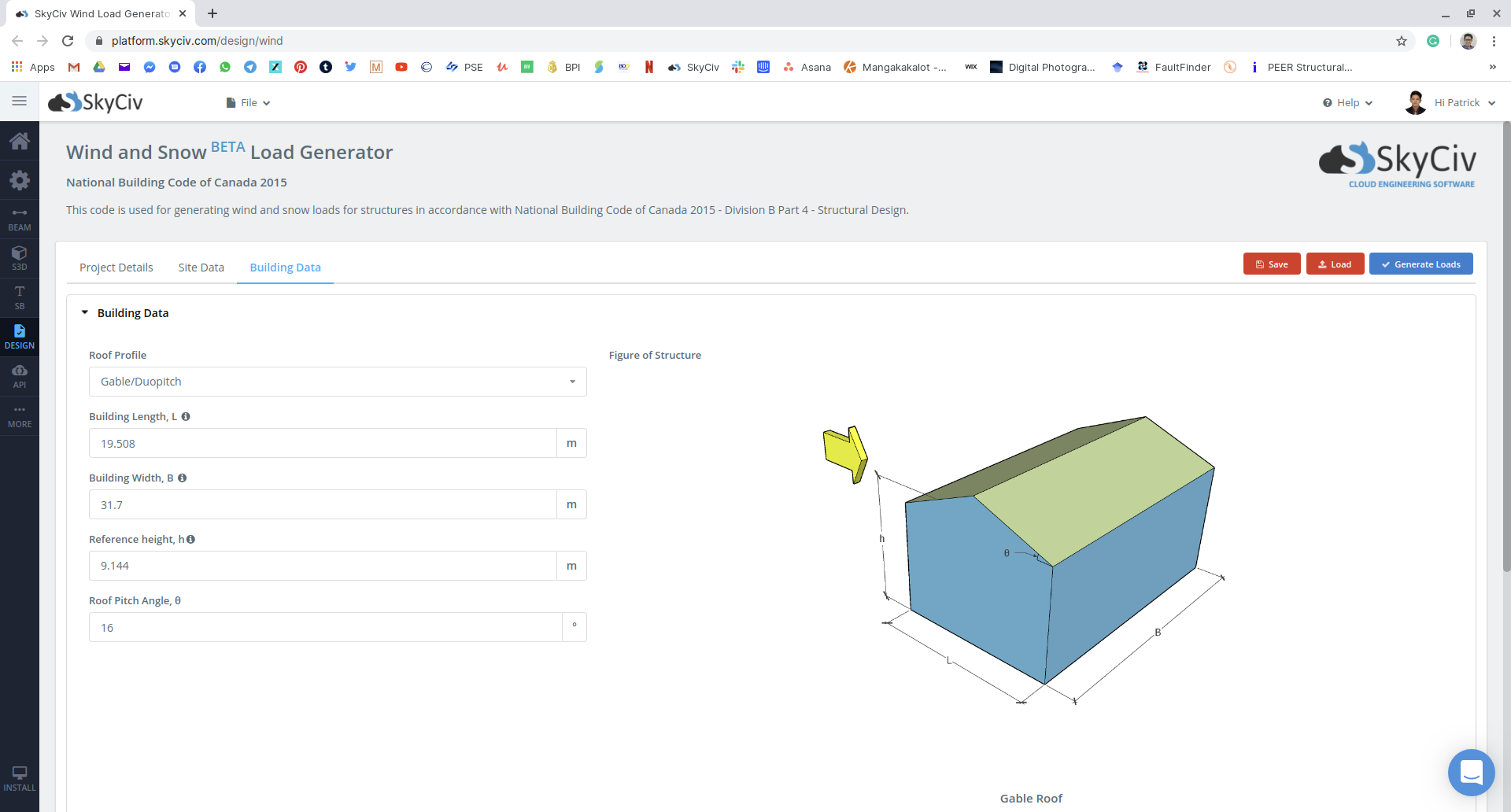
Figure 16: Building and snow parameter input on SkyCiv Load Generator module using our example.
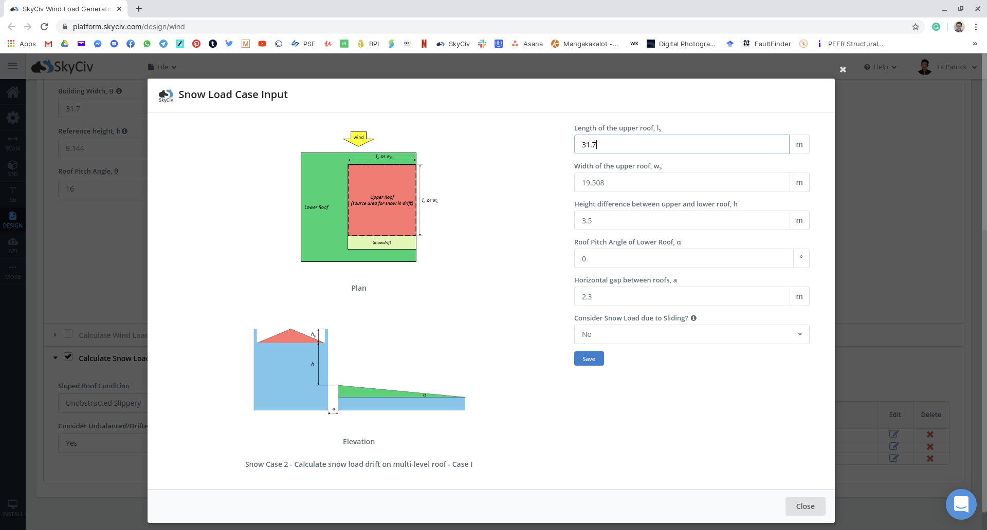
Figure 17: Snow load input for multiple unbalanced cases for the example.
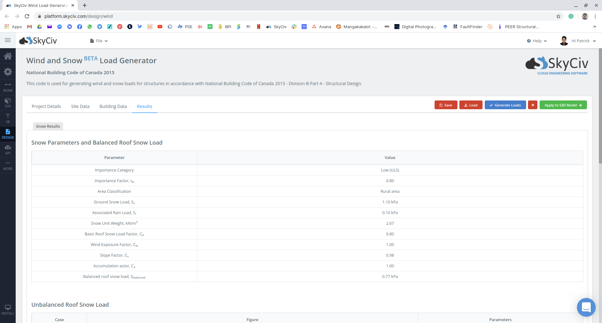
Figure 18: Summary of snow load parameters used and the balanced snow load to be applied to the structure.
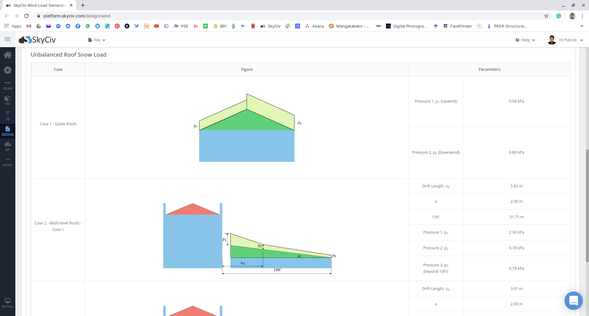
Figure 19: Summary of unbalanced snow load results.
Snow load calculations in the SkyCiv Load Generator module are supported by reference codes such as ASCE 7-10, 7-16, EN 1991-1-3, NBCC 2015, and AS/NZS 1170.3, and is available on the Standalone (Load Generator only) and Professional accounts. Familiar with programming and API’s? This functionality can be automated with use of the SkyCiv API.

Structural Engineer, Product Development
MS Civil Engineering
References:
- National Research Council of Canada. (2015). National Building Code of Canada, 2015. National Research Council of Canada.
Note:
- NBCC code reference for the “Basic Roof Snow Load Factor” — look for 4.1.6.2 Sentence (2)
- NBCC code reference for the “Wind Exposure Factor” — look for 4.1.6.2 Sentences (3) and (4)
- NBCC code reference for the “Slope Factor” — look for 4.1.6.2 Sentences (5), (6), and (7)
- NBCC code reference for the “Accumulation Factor” — look for 4.1.6.2 Sentence (8), 4.1.6.5 for Multi-level roofs, 4.1.6.6 for roofs with gap, and 4.1.6.9 for gable roofs