This article discusses two reinforced concrete slab design examples, including one-way and two-way bending. The main goal is to compare the results obtained between hand calculations and SkyCiv Plate Design Module. We will use Eurocode 2 for Reinforced Concrete Structures.
Construction codes have similar approaches when defining the typical cases for slabs. If you want to learn a bit more on this topic, we suggest you to read the following articles regarding slab design ACI Slab Design Example and Comparison with SkyCiv and Australian Standards AS3600 Slab Design Example and Comparison with SkyCiv
One-Way Slab Design Example
The first case to analyse is a small one-floor building (Figure 1, Figure 2) which has a slab behaviour described as in one-direction.
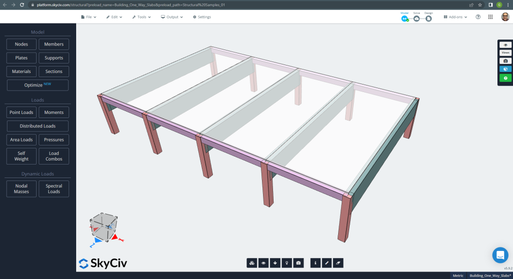
Figure 1. One-way slabs in a small building example. (Structural 3D, SkyCiv Cloud Engineering).
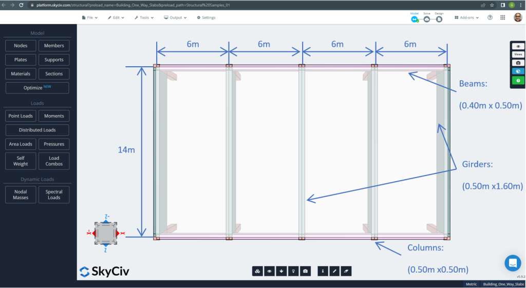
Figure 2. One-way slabs in a small building example (plan dimensions). (Structural 3D, SkyCiv Cloud Engineering).
For the slab example, in summary, the material, elements properties, and loads to consider :
- Slab type classification: One – way behaviour \(\frac{L_2}{L_1} > 2 ; \frac{14m}{6m}=2.33 > 2.00 \) Ok!
- Building occupation: Residential use
- Slab thickness \(t_{slab}=0.25m\)
- Reinforced concrete density \(\rho_w = 25 \frac{kN}{m^3}\)
- Concrete characteristic compressive strength at 28 days (C25\30) \(fck = 25 MPa \)
- Slab Self-Weight \(Dead = \rho_w \times t_{slab} = 25 \frac{kN}{m^3} \times 0.25m = 6.25 \frac {kN}{m^2}\)
- Super-imposed dead load \(SD = 3.0 \frac {kN}{m^2}\)
- Live load \(L = 2.0 \frac {kN}{m^2}\)
Hand calculations according to EN-2
In this section, we will calculate the required reinforced steel rebar using the reference of the Eurocode Standard. We first obtain the total factored bending moment to be carried out by the slab’s unitary width strip.
- Dead load, \(g = (3.0 + 6.25) \frac{kN}{m^2} \times 1 m = 9.25 \frac{kN}{m}\)
- Live load, \(q = (2.0) \frac{kN}{m^2} \times 1 m = 2.0 \frac{kN}{m}\)
- Ultimate load, \(Fd = 1.35\times g + 1.5\times q = (1.35\times 9.25 + 1.5\times 2.0)\frac{kN}{m} =15.5 \frac{kN}{m} \)
Before obtaining the steel reinforcement area, we have to check the span-effective depth ratios. Two main cases:
| Structural System | Basic span-effective depth ratio | ||
|---|---|---|---|
| Factor for structural sistem K | Concrete highly stressed %(\(\rho = 1.5 )\) | Concrete lightly stressed %(\(\rho = 0.5 )\) | |
| 1. End span of continuous beam or one-way continuous slab or two-way slab continuous over one long side | 1.3 | 18 | 26 |
| 2. Interior span of continuous beam or one-way or two-way spanning slab | 1.5 | 20 | 30 |
The most critical case is for number one, so, we select a ratio of 26.
- \(t_{min}=\frac{L}{SE}+cover+0.5\dot bar_{diameter}=\frac{6m}{26}+0.025m+0.5\times 12mm=0.26m \) ~ \(0.25m\). The overall thickness is still adequate, Ok!
Now, it is time to use the table for one-way continuous slabs:
| End support condition | At first interior support | At middle of interior spans | At interior supports | ||||
|---|---|---|---|---|---|---|---|
| Pinned | Continuous | ||||||
| Outer support | Near middle of end span | End support | End span | ||||
| Moment | 0 | 0.086FL | – | 0.075FL | – | 0.063FL | – |
| 0.04FL | 0.086FL | 0.063FL | |||||
| Shear | 0.4F | – | – | – | |||
| 0.46F | 0.6F | 0.5F | |||||
Where:
- L is the effective span
- F is the total ultimate load in the span (1.35Gk + 1.5Qk; Gk is the dead load and Qk the live load, respectively)
It will be explained only one case (continuous end support) and the rest will show in the following table.
- \(F=Fd\times L = 15.5 \frac{kN}{m} \times 6m = 93.0 kN \)
- \(M=0.04FL=0.04 \times 93.0 kN \times 6m= -22.32{kN}{m}\)
- \(d =230 mm \)
- \(K=\frac{M}{{b}{d^2}{f_{ck}}}=\frac{22.32\times 10^6 {N}{mm}}{{1000mm}\times{(230 mm)^2}\times {25 \frac{N}{mm^2}}}=0.016877\)
- \(l_a = 0.95 \)
- \(z=l_a \times d = 0.95\times 230mm = 218.50 mm\)
- \(A_s = \frac{M}{{0.87}{f_{yk}}{z}}=\frac{22.32\times 10^6 {N}{mm}}{0.87\times 500 {N}{mm^2} \times {218.50mm} = 234.83 mm^2 }\)
- \(A_{s,min}=0.0013{b}{d}=0.0013\times 1000mm \times 230 mm =299 mm^2\)
- \(A_{st}=max(A_s, A_{s,min}) = max(234.83, 299) mm^2 = 299 mm^2 \)
| Moments | Exterior Negative Left | Exterior Positive | Exterior Negative Right | Interior Negative Left | Interior Positive | Interior Negative Right |
|---|---|---|---|---|---|---|
| M value, kN-m | 22.32 | 35.15 | 41.85 | 48.00 | 35.15 | 35.15 |
| K | 0.0168 | 0.0266 | 0.03164 | 0.0362 | 0.0266 | 0.0266 |
| z, mm | 218.50 | 218.50 | 218.50 | 218.50 | 218.50 | 218.50 |
| \(A_s, mm^2\) | 234.83 | 369.815 | 440.31 | 505.011 | 369.815 | 369.815 |
| \(A_{s,min},mm^2\) | 299.00 | 299.00 | 299.00 | 299.00 | 299.00 | 299.00 |
| \(A_{st} {mm^2}\) | 299.00 | 369.815 | 440.31 | 505.011 | 369.815 | 369.815 |
The next move is to calculate the reinforcement rebar steel using the Plate Design Module in SkyCiv. Please, keep reading the following section!.
If you are new at SkyCiv, Sign up and test the software yourself!
SkyCiv S3D Plate Design Module Results
This section deals with obtaining the steel reinforcement area but just using the software, the Plate Design Module. In a concise way, we will only show the results or important information through images.
Before analyzing the model, we must define a plate mesh size. Some references (2) recommend a size for the shell element of 1/6 of the short span or 1/8 of the long span, the shorter of them. Following this value, we have \(\frac{L2}{6}=\frac{6m}{6} = 1m \) or \(\frac{L1}{8}=\frac{14m}{8}=1.75m \); we take 1m as a maximum recommended size and 0.50m applied mesh size.
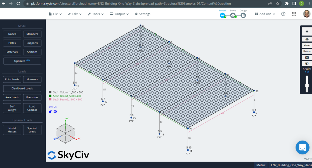
Figure 3. Plate meshed. (Structural 3D, SkyCiv Cloud Engineering).
Once we improved our analytical structural model, we run a linear elastic analysis. When designing slabs, we have to check if the vertical displacement are less than the maximum allowed by code. Eurocode 2 stablished a maximum serviciability vertical displacement of \(\frac{L}{250}=\frac{6000mm}{250}=24.0 mm\).
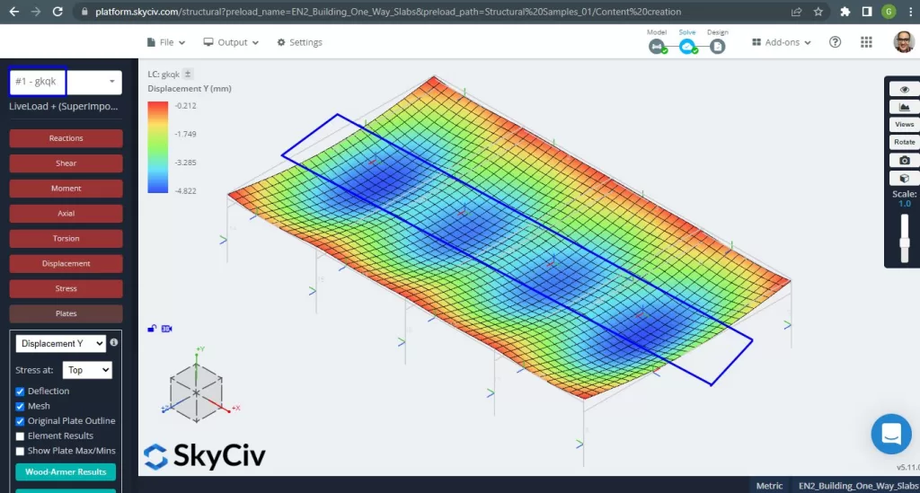
Figure 4. Vertical displacement, maximum values at center of spans. (Structural 3D, SkyCiv Cloud Engineering).
Comparing the maximum vertical displacement against the code-referenced value, the slab’s stiffness is adequate. \(4.822 mm < 24.00mm\).
The maximum moments in the slab’s spans are located for positive in the center and for negative at the exterior and interior supports. Let’s see these moments values in the following images.
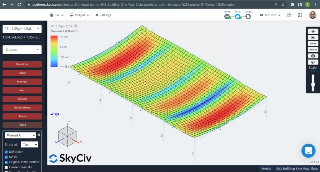
Figure 5. Bending moments in X direction. (Structural 3D, SkyCiv Cloud Engineering).

Figure 6. Bending moments in Y direction. (Structural 3D, SkyCiv Cloud Engineering).
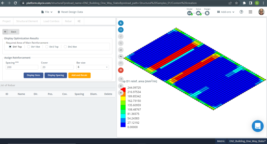
Figure 7. Steel Reinforcement for direction X at top. (Structural 3D, SkyCiv Cloud Engineering).
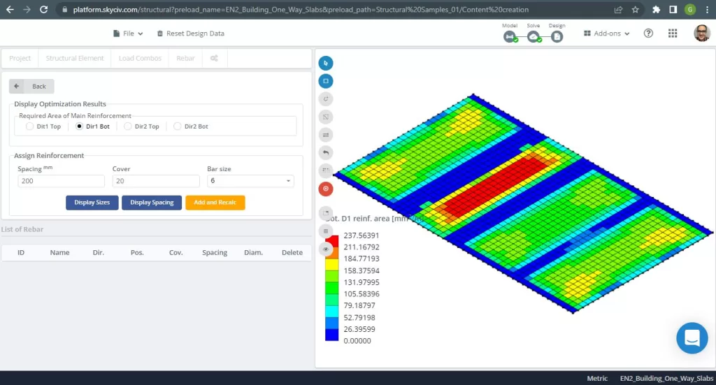
Figure 8. Steel Reinforcement for direction X at bottom. (Structural 3D, SkyCiv Cloud Engineering).

Figure 9. Steel Reinforcement for direction Y at top. (Structural 3D, SkyCiv Cloud Engineering).
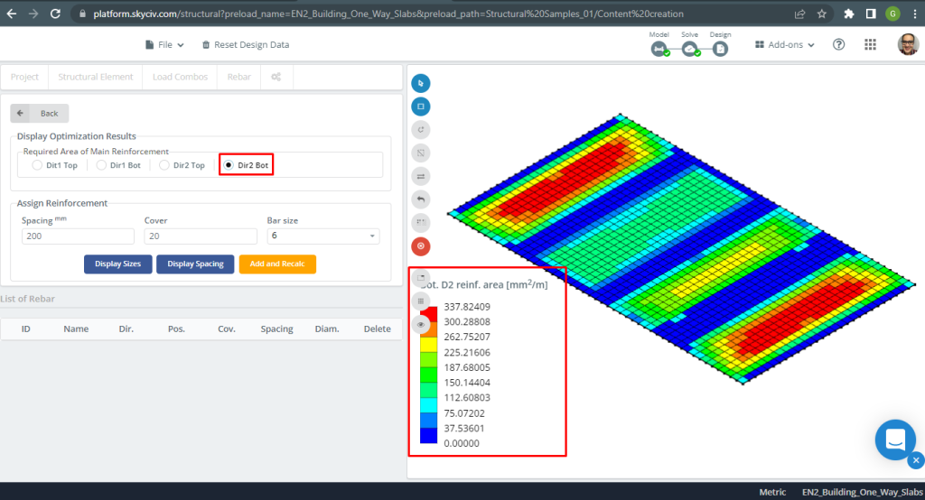
Figure 10. Steel Reinforcement for direction Y at bottom. (Structural 3D, SkyCiv Cloud Engineering).
Results comparison
The last step in this one-way slab design example is compare the steel rebar area obtained by S3D analysis (local axes “2”) and handcalculations.
| Moments and steel area | Exterior Negative Left | Exterior Positive | Exterior Negative Right | Interior Negative Left | Interior Positive | Interior Negative Right |
|---|---|---|---|---|---|---|
| \(A_{st, HandCalcs} {mm^2}\) | 299.00 | 369.82 | 440.31 | 505.011 | 369.82 | 369.82 |
| \(A_{st, S3D} {mm^2}\) | 308.41 | 337.82 | 462.61 | 462.61 | 262.75 | 308.41 |
| \(\Delta_{dif}\) (%) | 3.051 | 8.653 | 4.820 | 8.400 | 28.95 | 16.610 |
We can see that the results of the values are very close to each other. This means the calculations are correct!
If you are new at SkyCiv, Sign up and test the software yourself!
Two-way Slab Design Example
SkyCiv 3D Plate Design Module is a powerful software that can analyze and design any type of building you can imaging. For the second design slab example, we’ve decided to run a flat slab system (figure 11).
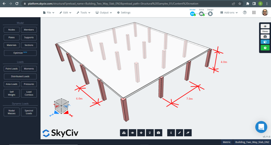
Figure 11. One-way slabs in a small building example. (Structural 3D, SkyCiv Cloud Engineering).
For the slab example, in summary, the material, elements properties, and loads to consider :
- Slab type classification: Two – way behaviour \(\frac{L_2}{L_1} \le 2 ; \frac{7m}{6m}=1.17 \le 2.00 \) Ok!
- Building occupation: Residential use
- Slab thickness \(t_{slab}=0.30m\)
- Reinforced concrete density \(\rho_w = 25 \frac{kN}{m^3}\)
- Concrete characteristic compressive strength at 28 days (C25\30) \(fck = 25 MPa \)
- Slab Self-Weight \(Dead = \rho_w \times t_{slab} = 25 \frac{kN}{m^3} \times 0.30m = 7.5 \frac {kN}{m^2}\)
- Super-imposed dead load \(SD = 3.0 \frac {kN}{m^2}\)
- Live load \(L = 2.0 \frac {kN}{m^2}\)
Hand calculations according EN-2
The first step is define the total ultimate load:
- Dead load, \(g = (3.0 + 7.5) \frac{kN}{m^2} \times 7 m = 73.50 \frac{kN}{m}\)
- Live load, \(q = (2.0) \frac{kN}{m^2} \times 7 m = 14.00 \frac{kN}{m}\)
- Ultimate load, \(Fd = 1.35\times g + 1.5\times q = (1.35\times 73.50 + 1.5\times 14.00)\frac{kN}{m} =120.225 \frac{kN}{m} \)
For hand calculation, the structure has to be divided into a series of equivalent frames. We can use the following methods to reach up this goal:
- Moment distribution (Hardy Cross Method) for frame analysis.
- Stiffness method for frame analysis on computer. Try our Stiffness Matrix Calculator.
- A simplified method using the moments coefficients for one-way direction adjusted to the following requirements (We selected this method due the simplicity of the model analyzed):
- The lateral stability is not dependent on the slab-column connections (We don’t analyze the building for lateral loads);
- There are at least three rows of panels of approximately equal span in the direction being considered (We have four and three rows of panels in both main directions);
- The bay size exceeds \(30m^2\) (Our model area is \(42m^2\)
The thickness selected for the slab example is greater than the maximum minimum value for fire resistance indicated in the table below.
| Standard fire resistance | Minimum dimensions (mm) | |
|---|---|---|
| Slab thickness, hs | Axis distance, a | |
| REI 60 | 180 | 15 |
| REI 90 | 200 | 25 |
| REI 120 | 200 | 35 |
| REI 240 | 200 | 50 |
In this section, we will develop only the calcs for the longitudinal direction and column strip (feel free to calculate for another direction, the transverse, and for middle strips). Before going deep in numbers, first we have to divide in strips: middle and column. (For more details about design strips, check this SkyCiv article: Design slabs with ACI-318).
- Column strip width: \(6m/4 = 1.50m\)
- Middle strip width: \(7m – 2\times 1.50m = 4.0m\)
EC2 allows assigning moments in each design strip according to the following table
| Column strip | Middle strip | |
|---|---|---|
| Negative moment at edge column | 100% but no more than \(0.17{b_e}{d^2}{f_{ck}}\) | 0 |
| Negative moment at internal column | 60-80% | 40-20% |
| Positive moment in span | 50-70% | 50-30% |
We selected the percentages of moments for the column strip being analyzed:
- Negative moment at edge column: 100%.
- Negative moment at internal column: 80%
- Positive moment in span: 70%
Total design strips moments calculation:
| End support condition | At first interior support | At middle of interior spans | At interior supports | ||||
|---|---|---|---|---|---|---|---|
| Pinned | Continuous | ||||||
| Outer support | Near middle of end span | End support | End span | ||||
| Moment | 0 | 0.086FL | – | 0.075FL | – | 0.063FL | – |
| 0.04FL | 0.086FL | 0.063FL | |||||
| Shear | 0.4F | – | – | – | |||
| 0.46F | 0.6F | 0.5F | |||||
Where:
- L is the effective span
- F is the total ultimate load in the span (1.35Gk + 1.5Qk; Gk is the dead load and Qk the live load, respectively)
It will be explained only one case (continuos end support) and the rest will show in the following table.
- \(F=Fd\times L = 120.225 \frac{kN}{m} \times 6m = 721.35 kN \)
- \(M=0.04FL=0.04 \times 721.35 kN \times 6m= -173.124 {kN}{m}\)
- \(d =280 mm \)
- \(K=\frac{M}{{b}{d^2}{f_{ck}}}=\frac{173.124\times 10^6 {N}{mm}}{{1500mm}\times{(280 mm)^2}\times {25 \frac{N}{mm^2}}}=0.012637\)
- \(l_a = 0.95 \)
- \(z=l_a \times d = 0.95\times 280mm = 266.0 mm\)
- \(A_s = \frac{M}{{0.87}{f_{yk}}{z}}=\frac{173.124\times 10^6 {N}{mm}}{0.87\times 500 {N}{mm^2} \times {266.0mm} = 214.0523 mm^2 }\)
- \(A_{s,min}=0.0013{b}{d}=0.0013\times 1500mm \times 280 mm =546 mm^2\)
- \(A_{st}=max(A_s, A_{s,min}) = max(234.83, 546) mm^2 = 299 mm^2 \)
| Moments | Exterior Negative Left | Exterior Positive | Exterior Negative Right | Interior Negative Left | Interior Positive | Interior Negative Right |
|---|---|---|---|---|---|---|
| M value, kN-m | 173.124 | 191.125 | 260.064 | 298.281 | 191.125 | 218.429 |
| K | 0.05897 | 0.06500 | 0.0884 | 0.101 | 0.06500 | 0.0743 |
| z, mm | 266.00 | 266.00 | 266.00 | 266.00 | 266.00 | 266.00 |
| \(A_s, mm^2\) | 1498.366 | 1651.761 | 2247.55 | 2577.835 | 1651.761 | 1887.727 |
| \(A_{s,min},mm^2\) | 546.00 | 546.00 | 546.00 | 546.00 | 546.00 | 546.00 |
| \(A_{st} {mm^2}\) | 1498.366 | 1651.761 | 2247.55 | 2577.835 | 1651.761 | 1887.727 |
The next move is to calculate the reinforcement rebar steel using the Plate Design Module in SkyCiv. Please, keep reading the following section!
SkyCiv S3D Plate Design Module Results
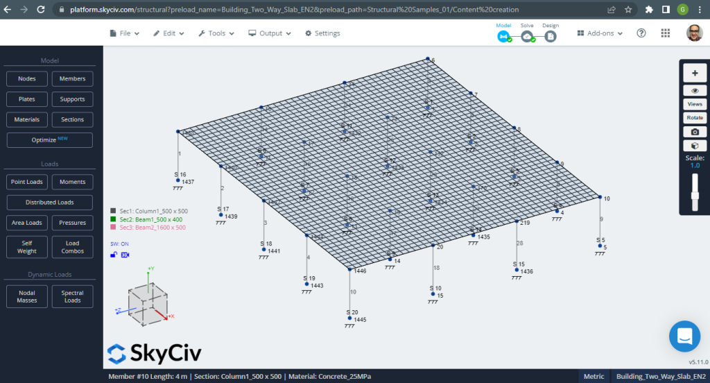
Figure 12. One-way slabs in a small building example. (Structural 3D, SkyCiv Cloud Engineering).
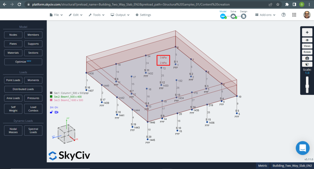
Figure 13. One-way slabs in a small building example. (Structural 3D, SkyCiv Cloud Engineering).
When designing slabs, we have to check if the vertical displacement are less than the maximum allowed by code. Eurocode stablished a maximum serviciability vertical displacement of \(\frac{L}{250}=\frac{6000mm}{250}=24.0 mm\).
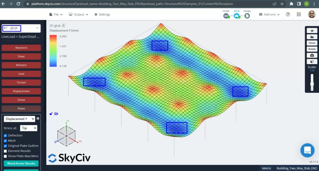
Figure 14. One-way slabs in a small building example. (Structural 3D, SkyCiv Cloud Engineering).
The image above gaves to us the vertical displacement. The maximum value is -4.148mm being less than the maximum allowed of -24mm. Therefore, the slab’s stiffeness is adequate.
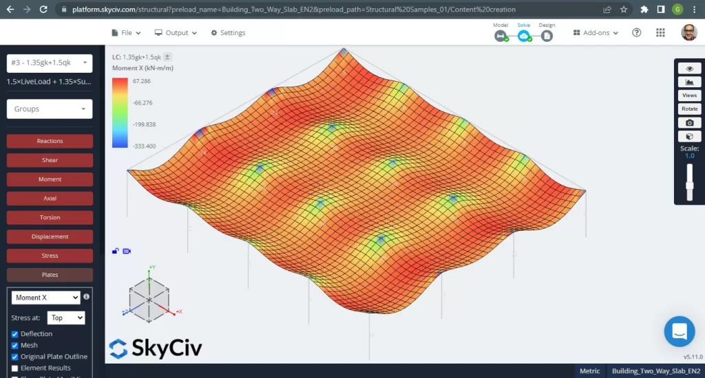
Figure 15. One-way slabs in a small building example. (Structural 3D, SkyCiv Cloud Engineering).
Images 15 and 16 consist of the bending moment in each main direction. Taking the moment distribution and values, the software, SkyCiv, can obtain then the total steel reinforcement area.

Figure 16. One-way slabs in a small building example. (Structural 3D, SkyCiv Cloud Engineering).
Steel reinforcement areas:
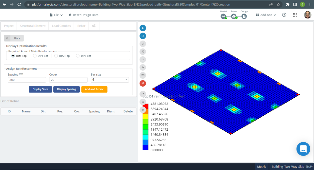
Figure 17. One-way slabs in a small building example. (Structural 3D, SkyCiv Cloud Engineering).
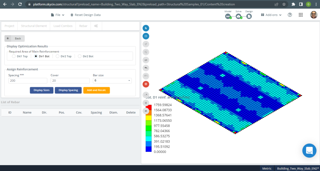
Figure 18. One-way slabs in a small building example. (Structural 3D, SkyCiv Cloud Engineering).
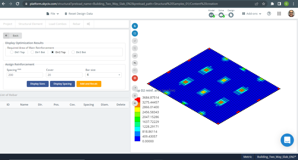
Figure 19. One-way slabs in a small building example. (Structural 3D, SkyCiv Cloud Engineering).
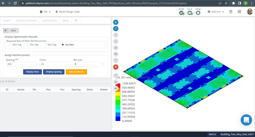
Figure 20. One-way slabs in a small building example. (Structural 3D, SkyCiv Cloud Engineering).
Results comparison
The last step in this two-way slab design example is to compare the steel rebar area obtained by S3D analysis and hand calculations.
Rebar steel for X direction and Column Strip
| Moments and steel area | Exterior Negative Left | Exterior Positive | Exterior Negative Right | Interior Negative Left | Interior Positive | Interior Negative Right |
|---|---|---|---|---|---|---|
| \(A_{st, HandCalcs} {mm^2}\) | 1498.366 | 1651.761 | 2247.55 | 2577.835 | 1651.761 | 1887.727 |
| \(A_{st, S3D} {mm^2}\) | 3889.375 | 1040.00 | 4196.145 | 4196.145 | 520.00 | 3175.00 |
| \(\Delta_{dif}\) (%) | 61.475 | 37.04 | 46.44 | 38.566 | 68.52 | 40.544 |
If you are new at SkyCiv, Sign up and test the software yourself!
References
- B. Mosley, R. Hulse, J.H. Bungey , “Reinforced Concrete Design to Eurocode 2”, Seventh edition, Palgrave MacMillan.
- Bazan Enrique & Meli Piralla, “Diseño Sísmico de Estructuras”, 1ed, LIMUSA.
- Eurocode 2: Design of concrete structures.