Flange plate moment connections are a vital part of steel construction, providing a secure way to join beams, columns, or girders and transfer axial and moment loads between them. These connections are designed to withstand the stresses placed upon them, ensuring the overall structure can handle the load conditions. To optimize the design of flange plate moment connections, engineers and designers can use different methodologies such as ASD and LRFD, as well as online connection design calculators like SkyCiv.
AISC standards provide guidance on the design of flange plate moment connections, but designers can also use other resources such as the SkyCiv connection design calculator. This online tool enables users to input various design parameters such as beam size, column size, connection type, and load conditions, and provides the necessary bolt size and spacing, plate thickness, and weld size for the connection.
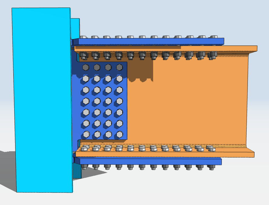
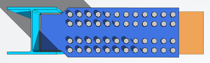
The flange plate moment connection typically consists of a steel plate that is bolted to the beam flange and welded to the column flange. If the frame is shop-assembled, an all-welded connection can be used instead. The web plate connection is also part of the overall flange plate moment connection, which is usually bolted at the beam web and welded to the column. The web plate resists the shear load while the flange plate resists the axial and moment loads.
Flange plate moment connections offer numerous benefits in steel construction. They are relatively simple and easy to fabricate and install, provide a high degree of flexibility in terms of the types of beams and columns that can be connected, and can be designed to withstand various load conditions such as service loads and extreme loads such as earthquakes and high winds.
Overall, flange plate moment connections are a critical component of steel construction, and engineers and designers can use different resources such as AISC standards and online connection design calculators like SkyCiv to optimize their designs. By using flange plate moment connections, engineers and designers can achieve reliable and secure connections that provide a safe and stable structure.
Elevation View
Top View
Now onto using the software.
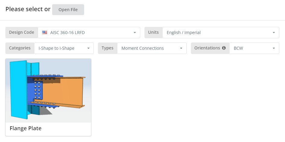
The Design Code can be AISC 360-16 ASD or LRFD. Units can be English/Imperial or SI/Metric. Orientation can either be BCF or BCW. Hover over the tooltip for more info. Now click the “Flange Plate” tile.
Project Tab
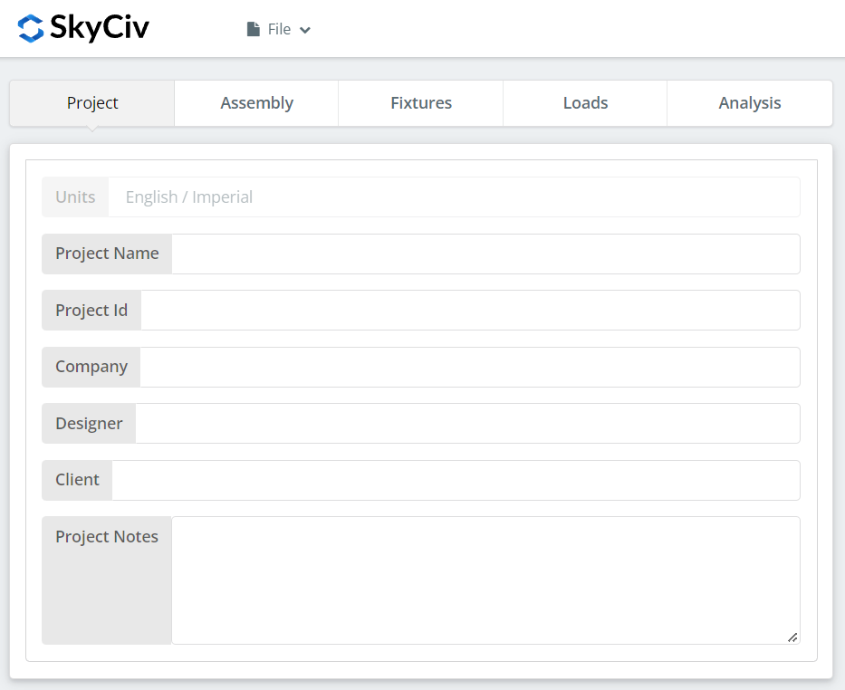
Here you can specify the details of the project you are currently working.
Assembly Tab
There are three tabs under Assembly. This is where you specify the Column, Beam, and Connection (Flange Plate and Web Plate) properties.
Column Tab
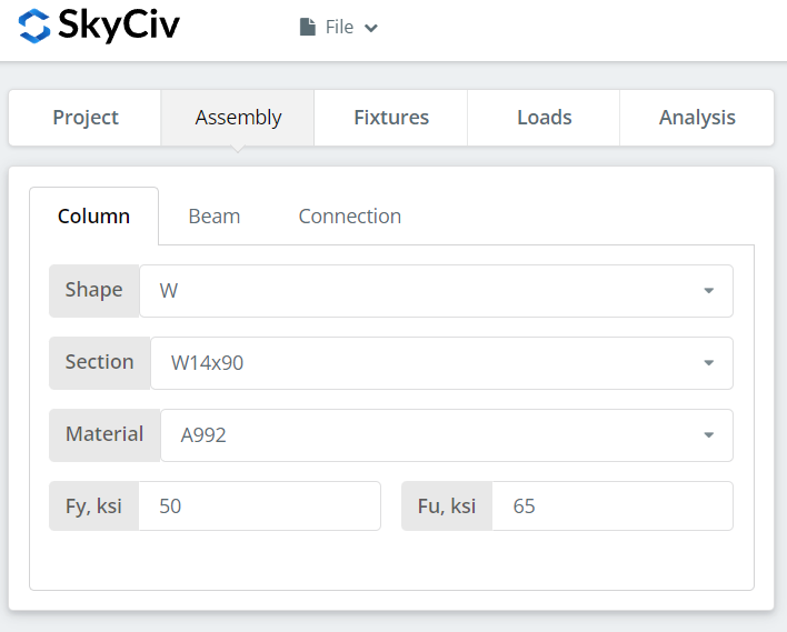
Here you can specify the section/shape of the column and its material grade. You can either choose A992 or A36 material. But if you are using a different material, you can choose Custom and manually input the Fy and Fu values.
Beam Tab
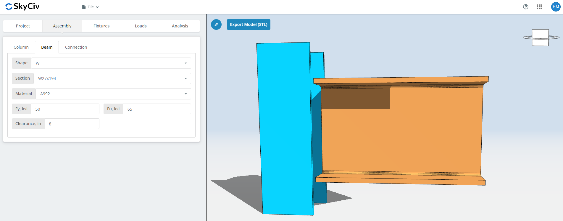
Similar to the column tab, here you can specify the beam section/shape and material grade. In addition, you can also specify the beam clearance.
Connection Tab – Flange Plate Button
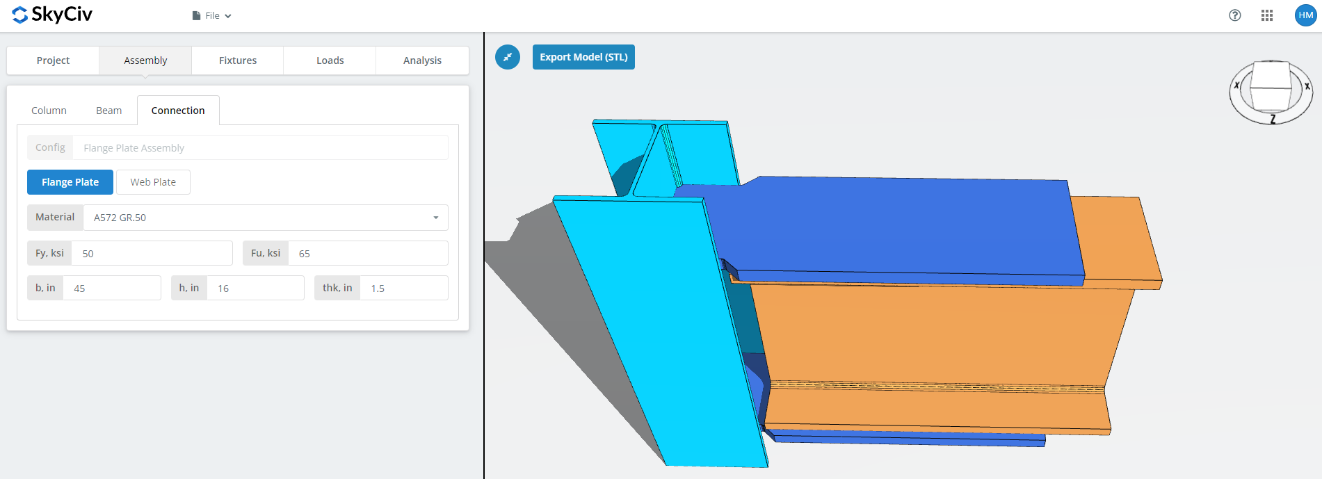
Here you can specify the properties of the flange plate. Material grade of A36, A992 or A572.GR50 but you can also specify “Custom” and manually input Fy and Fu. Set the b (width), h (height), and thk (thickness) of the plate. Now don’t forget to look closely at the 3D renderer and make sure the plate geometry make sense. Just make sure there is enough space for the bolts or welds that will be set on the fixtures tab later.
Connection Tab – Web Plate Button
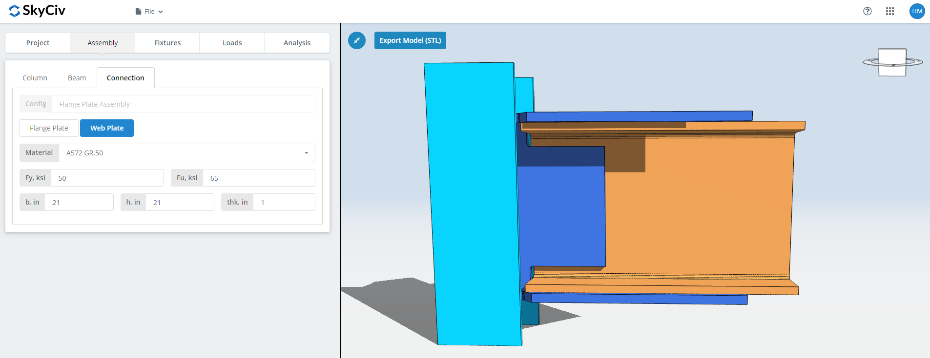
Here you can specify the properties of the web plate. Material grade of A36, A992 or A572.GR50 but you can also specify “Custom” and manually input Fy and Fu. Set the b (width), h (height), and thk (thickness) of the plate. Now don’t forget to look closely at the 3D renderer and make sure the plate geometry make sense. Just make sure there is enough space for the bolts or welds that will be set on the fixtures tab later.
Fixture 1 Tab
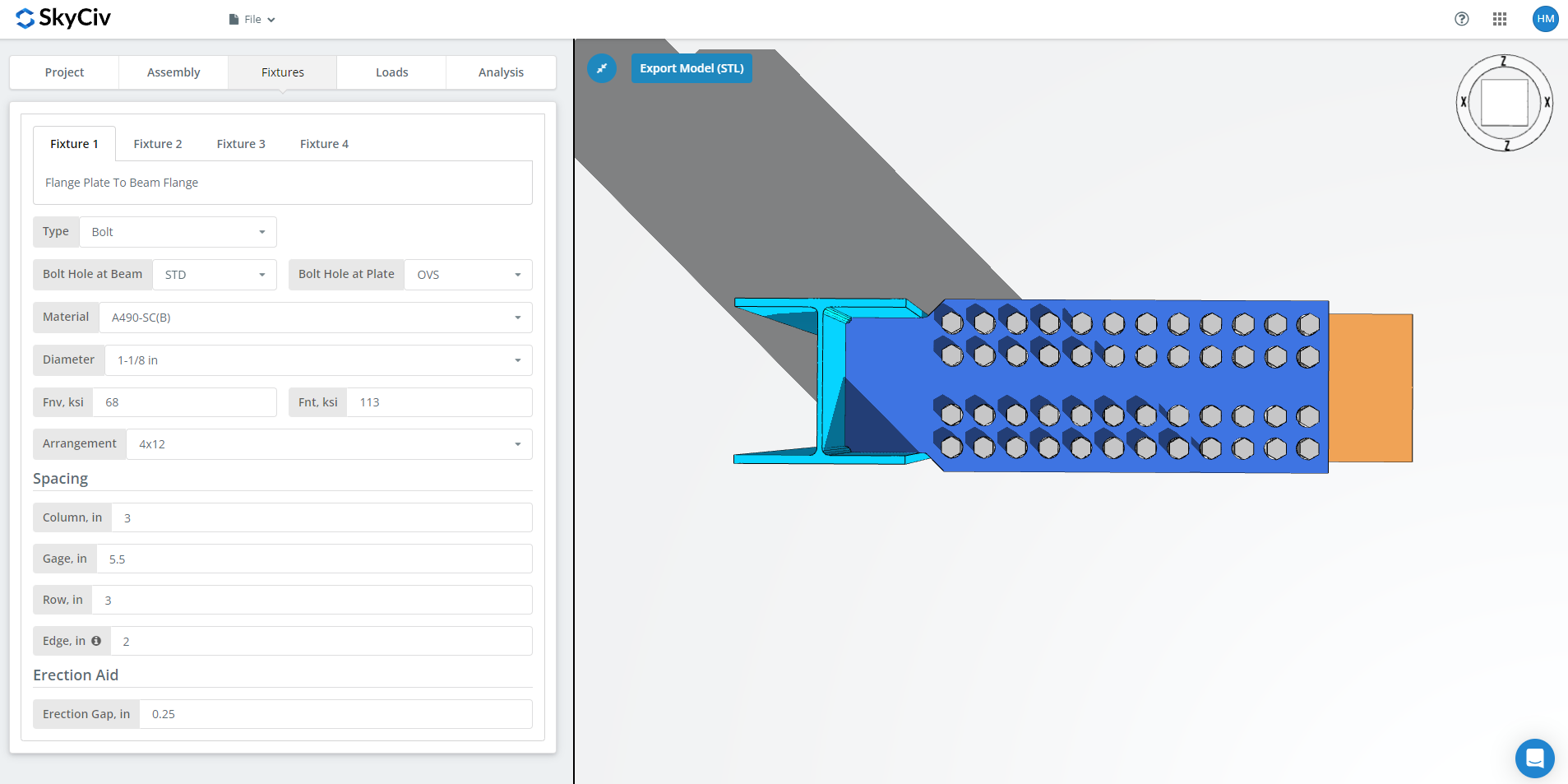
Here is where you can specify the flange plate to beam flange connection. You can either choose bolted or welded but for this demonstration, let’s choose a bolted one.
First, specify the bolt hole types at both beam flange and flange plate. Fabricators usually prefer using standard holes (STD) at member and oversized holes (OVS) at flange plate to allow better fitting at the field.
Next, select the bolt material or grade. You can choose either A307, A325, A490, or a Custom input. N or X bolts for bearing-type connections and SC for slip critical connections. Note that slip critical connections generally have lesser bolt capacity. You should only use SC when there is a presumed slip in the direction of the force. In this specific example, if you use OVS holes at any of the beam or plate, the bolt will be automatically checked as slip critical. As for N versus X, X has a larger bolt shear capacity but you will have to make sure that bolt threads are excluded from the shear plane thus you will need to communicate this properly with the erector. And for SC(A) versus SC(B), SC(B) has a larger bolt capacity but you will also need a more thorough cleaning of the plies, for example, SSPC-SP6 or Commercial Blast Cleaning.
Next, specify the bolt diameter. You can choose from 5/8″ up to 1-1/2″ diameter or the equivalent metric units. Then, specify the bolt arrangement. You can choose up to 8 bolt rows and 12 bolt columns. Don’t forget to specify the bolt row spacing, bolt column spacing, and bolt gage as well. As for the “edge” input, this is the distance from the beam end to the first bolt column.
And finally, erection gap. As its name suggests, this is a gap to aid erection in the field. Just make sure you really need this gap since there is an equivalent decrease in bolt capacity.
Fixture 2 Tab
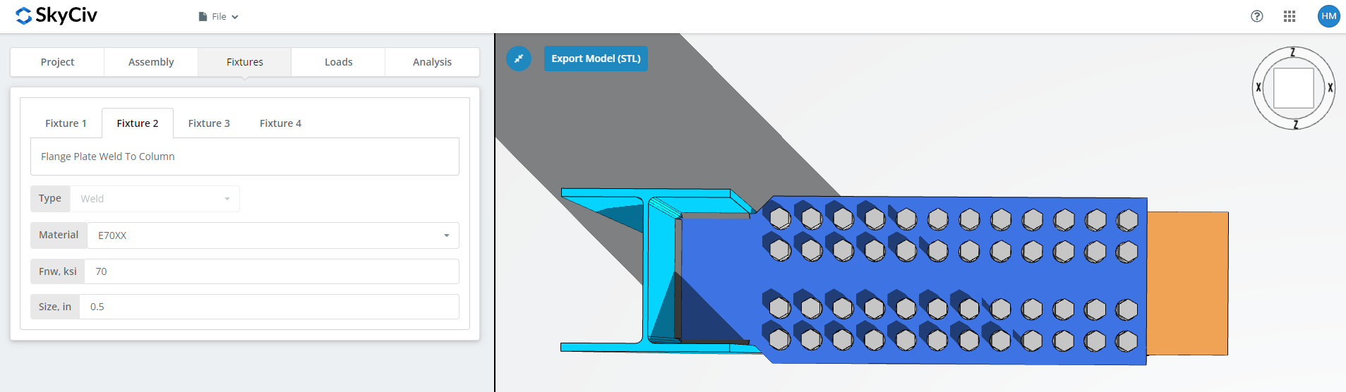
Here is where you can specify the flange plate to column web and flange (BCW) or column flange (BCF) connection. You can only choose welded here for flange plate connections. First, specify the weld material. There’s a couple of weld material options but if what you have is not there, you can use ‘Custom’ and manually input Fnw. And finally, don’t forget the weld size.
Fixture 3 Tab
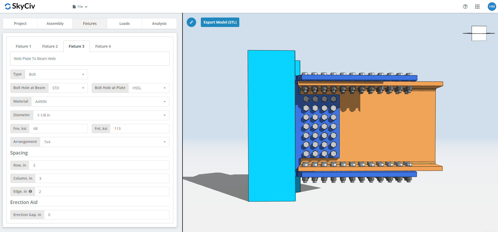
Here is where you can specify the web plate to column web or flange connection. You can either choose bolted or welded but for this demonstration, let’s choose a bolted one.
First, specify the bolt hole types at both beam web and web plate. Fabricators usually prefer using standard holes (STD) at member and horizontal short-slotted holes (HSSL) at web plate to allow better fitting at the field.
Next, select the bolt material or grade. You can choose either A307, A325, A490, or a Custom input. N or X bolts for bearing-type connections and SC for slip critical connections. Note that slip critical connections generally have lesser bolt capacity. You should only use SC when there is a presumed slip in the direction of the force. As for N versus X, X has a larger bolt shear capacity but you will have to make sure that bolt threads are excluded from the shear plane thus you will need to communicate this properly with the erector. And for SC(A) versus SC(B), SC(B) has a larger bolt capacity but you will also need a more thorough cleaning of the plies, for example, SSPC-SP6 or Commercial Blast Cleaning.
Next, specify the bolt diameter. You can choose from 5/8″ up to 1-1/2″ diameter or the equivalent metric units. Then, specify the bolt arrangement. You can choose up to 12 bolt rows and 12 bolt columns. Don’t forget to specify the bolt row spacing and bolt column spacing as well. As for the “edge” input, this is the distance from the beam end to the first bolt column.
And finally, erection gap. As its name suggests, this is a gap to aid erection in the field. Just make sure you really need this gap since there is an equivalent decrease in bolt capacity.
Fixture 4 Tab
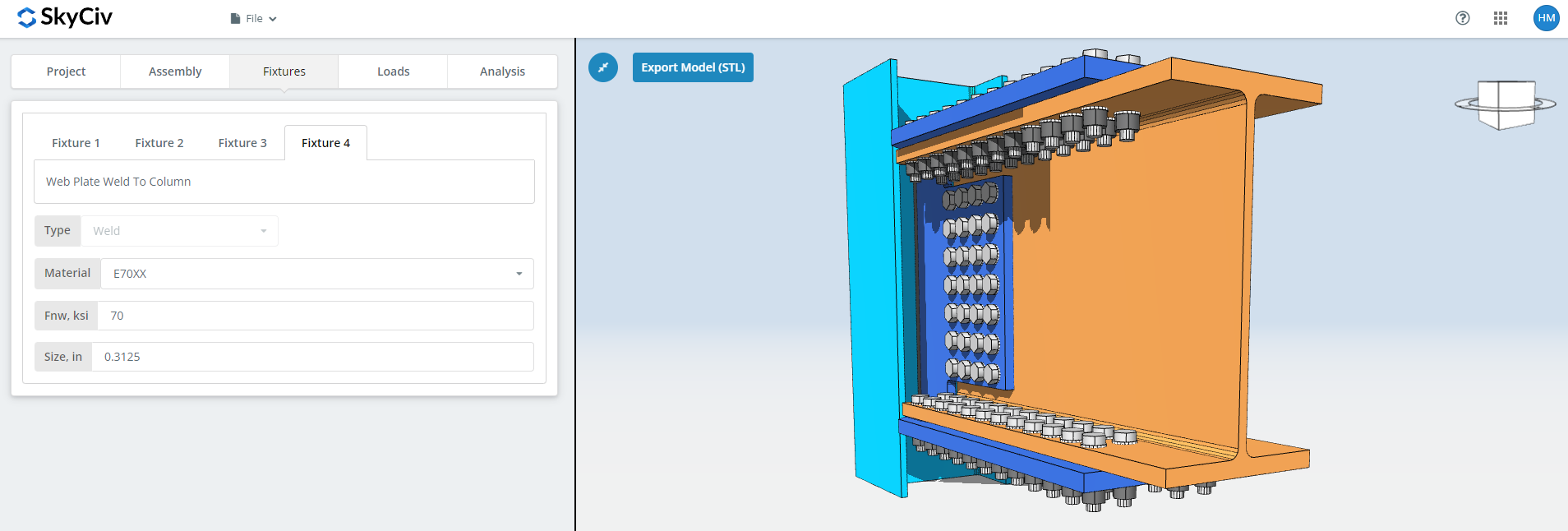
Here is where you can specify the web plate to column web or flange connection. You can only choose welded here for flange plate connections. First, specify the weld material. There’s a couple of weld material options but if what you have is not there, you can use ‘Custom’ and manually input Fnw. And finally, don’t forget the weld size.
Loads Tab
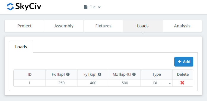
Don’t forget to input the horizontal axial load under ‘Fx’, vertical shear load under ‘Fy’, and strong axis moment load under ‘Mz’.
Analysis Tab
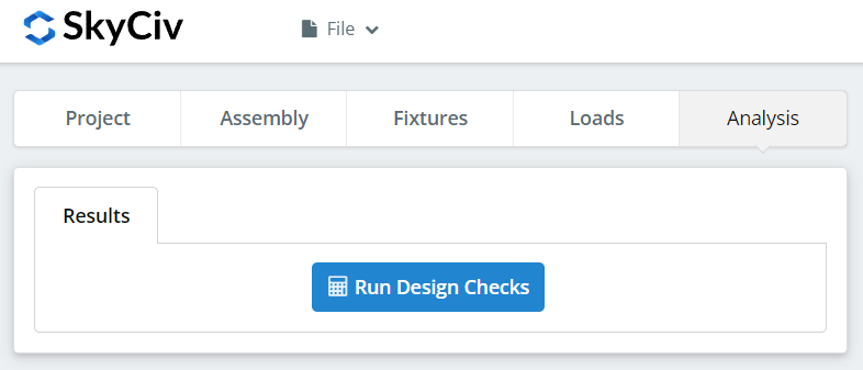
And finally, click “Run Design Checks”. If you missed any needed inputs on the previous tabs, this will notify you to fill in the missing inputs.
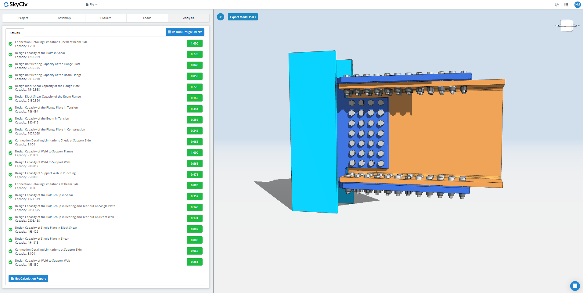
After clicking “Run Design Checks”, you can see a summary if your connection failed or not. If it failed, manually change the inputs in the previous tabs and then, click “Re-Run Design Checks”. When it’s finally okay, click “Get Calculation Report” to see the detailed report.
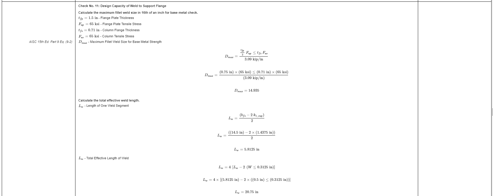
What you see above is a snippet of the detailed calculation report. As you can see, there is a reference to the AISC manual and/or specification. This should make it easier for the signing engineer to cross-check the calculations. Our calculations are very readable. It is written similar to how it’s written in the manual, specification, or design guides.
Here’s a PDF copy of the full detailed calculation report… Connection Design Report. Check it out!