Distributed loads (DL’s) are forces that act over a span and are measured in force per unit of length (e.g. kN/m or kip/ft). They can be either uniform or non-uniform.
Applying a Distributed Load
DLs are applied to a member and by default will span the entire length of the member. Users however have the option to specify the start and end of the DL somewhere along the span.
DLs which are applied at an angle to the member can be specified by providing the X ,Y, Z components.
To apply a DL, go to the input menu on the left-hand side and click on the Distributed Load button. Users can also apply a DL to a member by first selecting a member, then right-clicking and selecting “Add Distributed Load”, which will bring you to the Distributed Load input screen with the member ID field already filled.
When applying the DL, users need to specify values for:
- Distributed Load ID – The numerical ID used to identify each DL.
- Member ID – The member where the DL is applied.
- Start X-Mag – The starting magnitude of the DL – this can be either in the global X-direction, or the member’s local X direction by changing the axis reference point.
- End X-Mag – The ending magnitude of the DL – this can be either in the global X-direction, or the member’s local X direction by changing the axis reference point.
- Start Y-Mag – The starting magnitude of the DL – this can be either in the global Y-direction, or the member’s local Y direction by changing the axis reference point.
- End Y-Mag – The ending magnitude of the DL – this can be either in the global Y-direction, or the member’s local Y direction by changing the axis reference point.
- Start Z-Mag – The starting magnitude of the DL in the Z direction – again this can be either Local Z or the member’s Local Z, depending on the Axis setting.
- End Z-Mag – The ending magnitude of the DL in the Z direction – again this can be either Local Z or the member’s Local Z, depending on the Axis setting.
- Start Position – The position along the member where the DL starts. Expressed as a %. Default = 0%
- Finish Position – The position along the member where the DL ends. Expressed as a %. Default = 100%
- Load Group – Loads can be grouped with Load Group numbers. The Load Groups can then be multiplied by a factor in the ‘Load Combos’ menu. Optional.
Advanced Settings
- Axes – Apply the DL along the global (default) or local axis. If Local, it may help to toggle on the Show Member Local Axis ON in your Visibility Settings, so that users can see the reference axis.
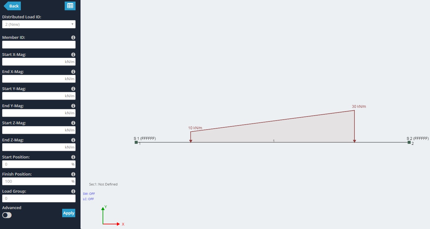
Example:
Here’s an example where the distributed load has a -10kN/m Start Y magnitude and a -30kN/m end Y magnitude. It also has a 20% start position and an 80% end position – showing that it does not extend the entire span of the member, but rather it starts 20% from the start and end node (1 and 2 respectively).
Local/Global Axes
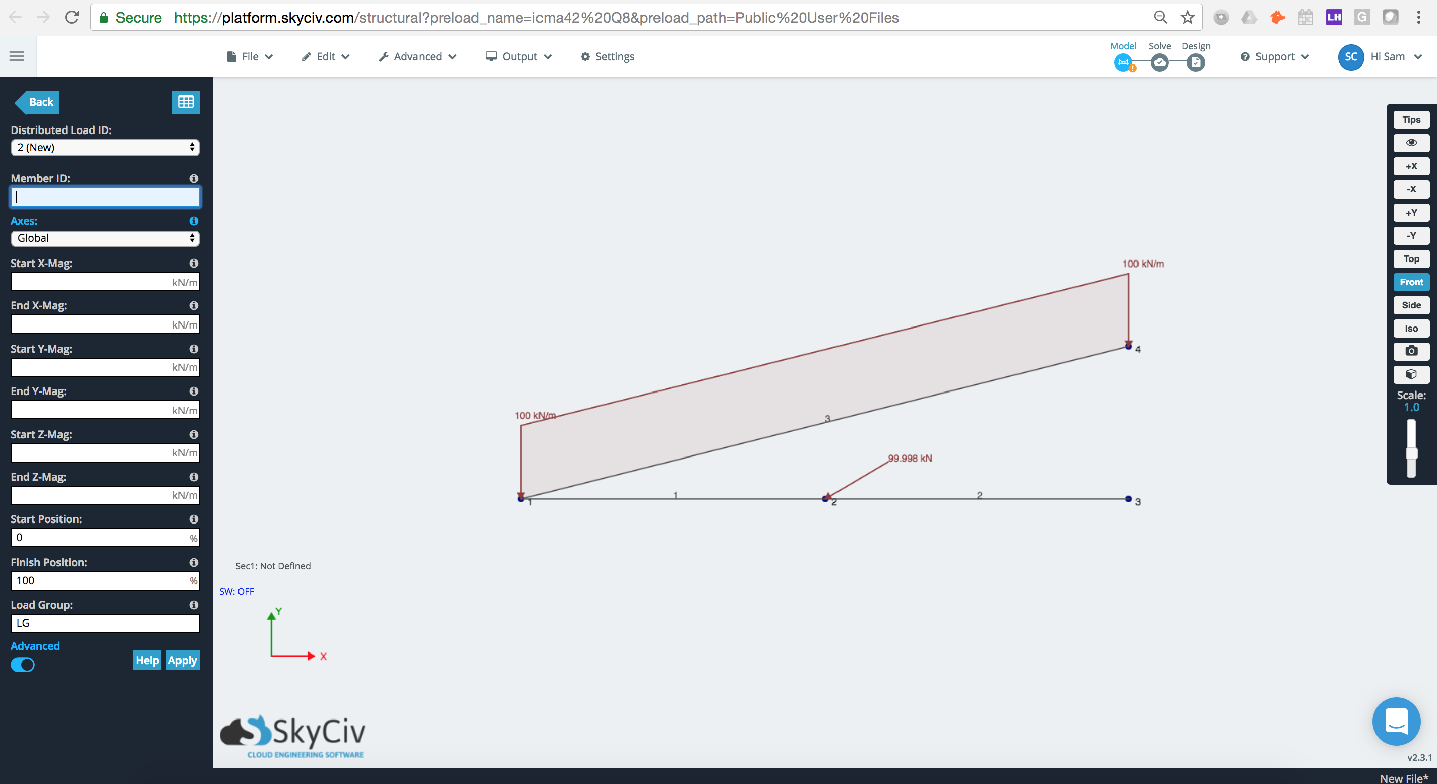
Global Axis
Here is an example of where member 3 has a 100kN/m distributed load applied to its Global axis. We can see the force here is applied directly in the global Y (down).
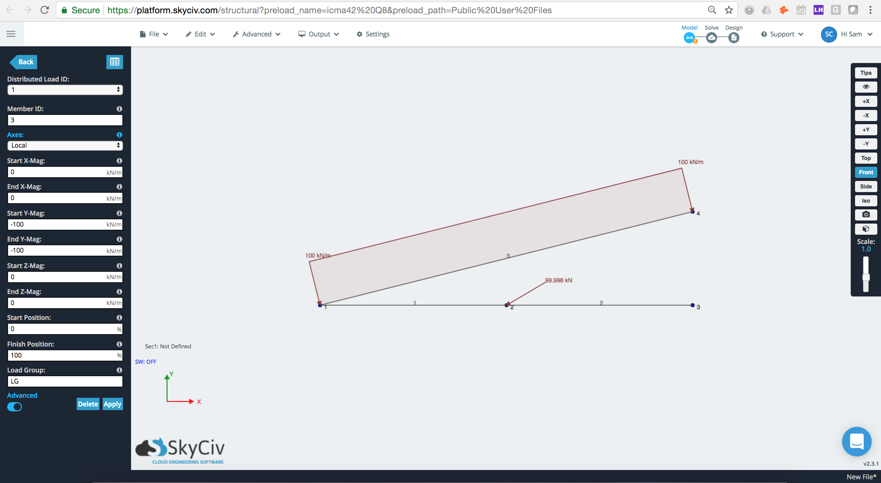
Local Axis
If we change the axes option to Local we can see that the distributed load has now been applied to the member’s local axis, where local Y is directly perpendicular to the member.
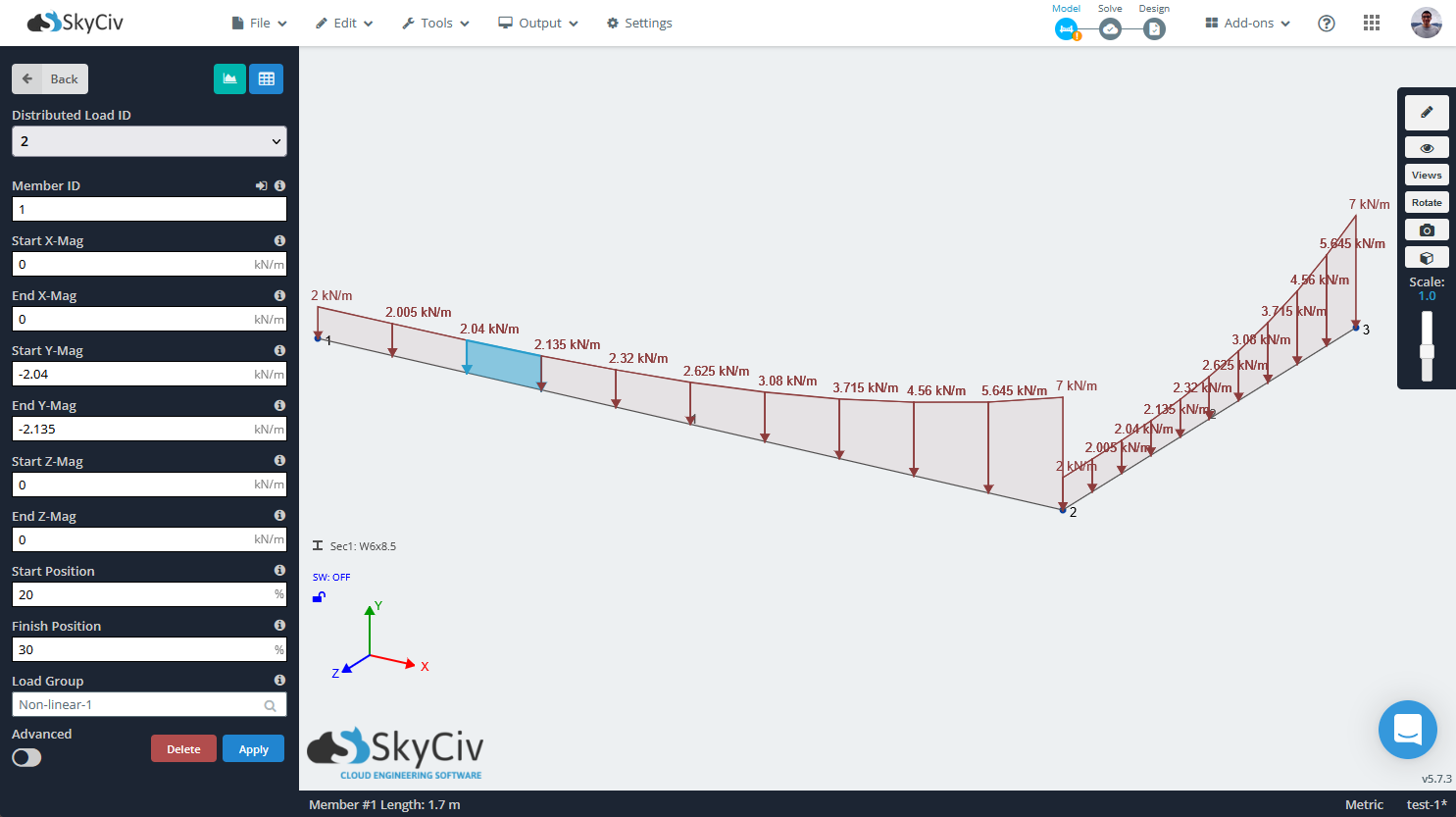
Applying a Non-Linear Distributed Load
Sometimes distributed loads (DLs) on the members of a structure follow a special distribution that cannot be idealized with a single constant one or even a nonuniform linear distributed load, and therefore non-linear distributed loads are needed. For those cases, it is possible to add a distributed load, which distribution is defined by a function in terms of the position along the member.
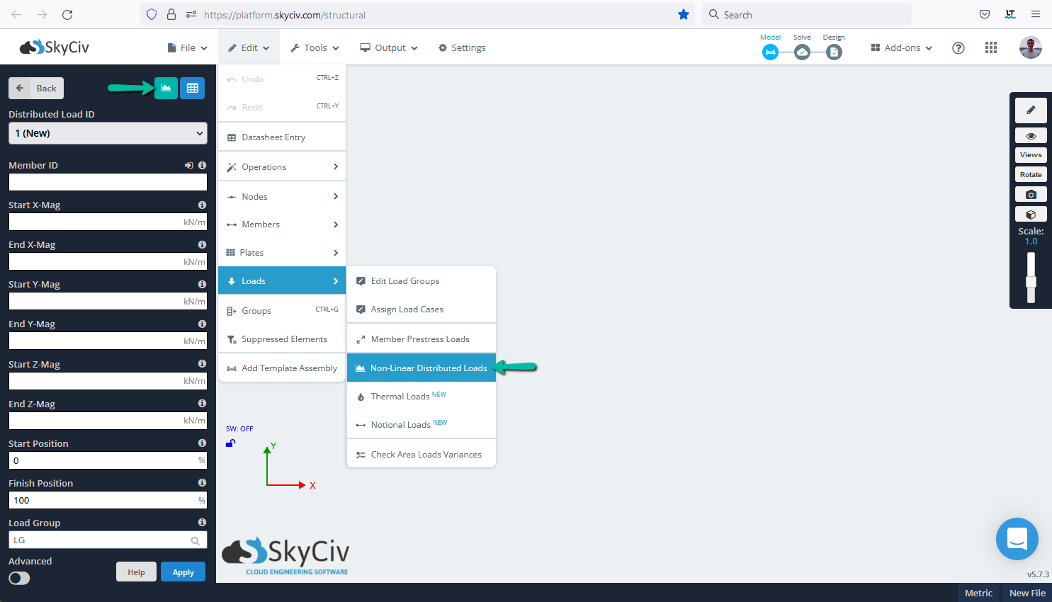
To apply a non-linear or equation defined DL, go to the input menu on the left-hand side and click on the Distributed Load button, then click the Add non-linear distributed load button. Users can also get to that menu by navigating the top bar to Edit > Loads > Non-linear distributed loads
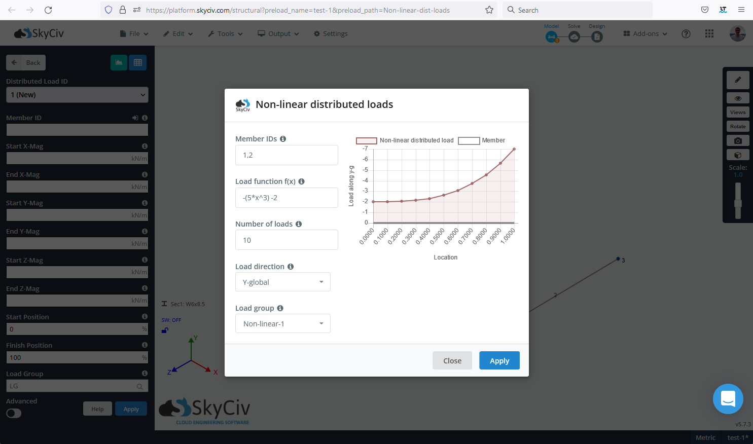
When applying the non-linear or equation defined DL, users need to specify values for:
- Member IDs: Comma separated IDs of the members to apply the non-linear or equation defined distributed load. It is possible to select the members before opening the window, and the input field will populate automatically.
- Load function: Function or equation in terms of the position along the member (x) that defines the load magnitude. The length of the members is normalized, running from 0 to 1.
- Number of loads: Represents the number of linear distributed loads the software will use for approximating the input function.
- Load direction: The same as with uniform and nonuniform distributed loads, the load can be applied in the local or global coordinated system.
- Load group: Name of the group to add the non-linear distributed load that will be created. By default, the software will create a new load group, but it is possible to select an existent load group or rename the new one.
After correctly inputting all the required values, the non-linear or equation defined distributed load will be added to the selected members, if the results are not as expected it is always possible to undo the changes and try again. As mentioned before, the input function is approximated by a number of linear distributed loads, you can find all of them as regular distributed loads.