A Guide to Unbraced Lengths, Slenderness and K Determination
SkyCiv’s 3D modeling and analysis tool, Structural 3D, allows users not only to run Linear and Non-Linear Analysis, but it also supports Buckling Analysis, which can sometimes be an afterthought in the structural engineering process. This article will discuss the parameters that are needed to determine a member’s resistance to buckling, and how that looks in SkyCiv Structural 3D. While there are other forms of buckling like lateral-torsional buckling, plate buckling, etc., this article will strictly look at buckling in compression members.
Buckling is a form of failure in compression members, which are usually columns. Consider the simple example of a soda can – when the can is compressed from either end, at a given force, there will a sudden deflection and it will collapse in on itself at some point along the length of the can. This is due to the occurrence of buckling. For structural elements, this failure mode needs to be considered, as it can have dire consequences on the structural integrity of the entire structure.
Slenderness Ratio
Members in which buckling becomes the governing failure mechanism are usually long and slender relative to their cross-section. We use something called the slenderness ratio to describe how “slender” a member is. The slenderness ratio is a quick and fairly simple ratio to calculate the buckling phenomena that occurs in a compression member. It is defined as:
slenderness ratio = KL/r
Where K is the effective length factor, l is the unbraced length of the member and r is the radius of gyration. The product KL is known simply as the effective length. The radius of gyration is found as follows:
r = sqrt(Ig/Ag)
Note: As approximations, it’s possible to use r = 0.3h for square and rectangular sections, and r = 0.25h for circular sections.
Controlling Unbraced Lengths and Restraints in the Software
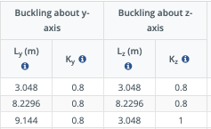
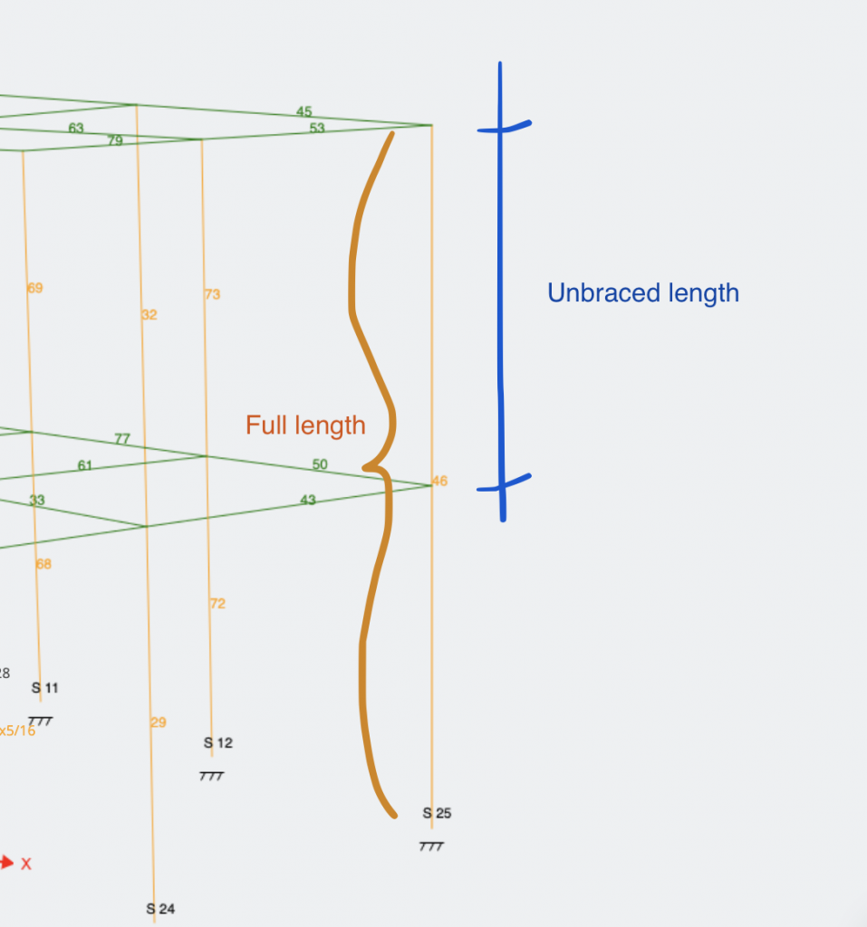
Unbraced length (unsupported length) is the largest distance along the member between brace points, or points at which the member is braced against deflection in the given direction. So, for a free-standing column, the unbraced length would be the full height/length. In many instances, the unbraced length of a member is less than the full length since there are members or other mechanisms bracing it along with the member. There are considered two key bracing lengths for the two axis of the members. In the SkyCiv software, we refer to these as Lz (major axis) and Ly (minor axis). These are are pre-filled in the software and can be modified in the Members table in the Member Design modules:
For example, the below column has a full length of 20ft, but the unbraced length in both axis directions is 10ft, since there is a beam bracing from both directions it at the midpoint of the column.
In the SkyCiv Design modules — Member Design and RC Design — the unbraced length is automatically calculated and populated in the Members table. Engineers can adjust and manipulate these values manually should any custom situations occur or special assumptions be made.
Effective Length Factor
Now that we know what the unbraced length is for a member, we can figure out what the effective length factor is. In SkyCiv Structural 3D, the effective length of a member is determined during a buckling analysis, where the eigenvalue of each member is calculated in order to determine critical buckling forces.
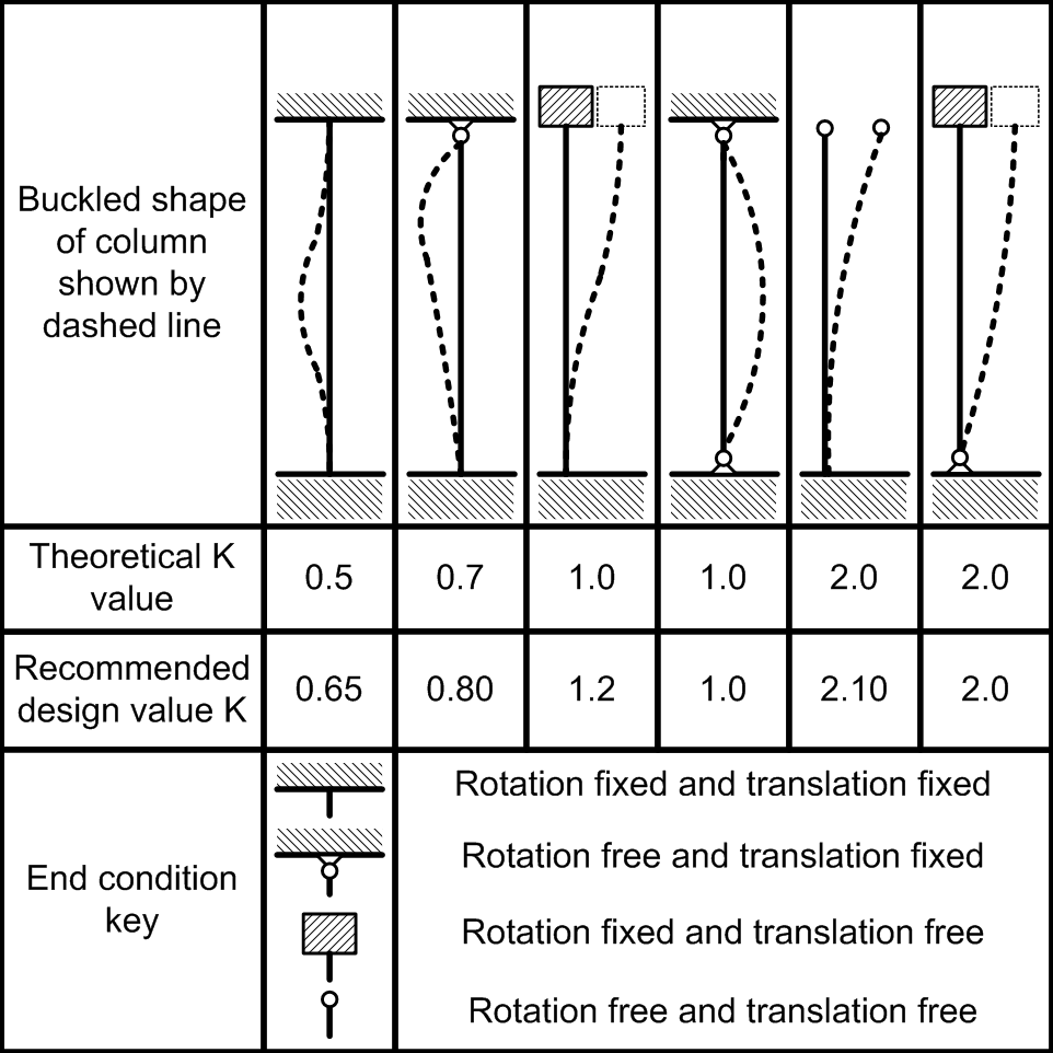
This basically just means that the solver will find the effective length of a member-based on finite element analysis. However, empirical K values are routinely used in practice and can be inferred from the commonly seen table below.
The effective length (K) factor of a member in compression is dependent on the support conditions at each end. The higher the K factor, the more the support conditions hurt the member’s resistance to buckling, and vice versa. Looking at the table below, we can see the effective length factors of common support situations with columns, or other compressive members:
 Simplified Effective Length (K-Factor) table:
 Simplified Effective Length (K-Factor) table:
| Boundary Condition | Recommended K Value |
|---|---|
| Fixed – Fixed | 0.65 |
| Fixed – Pinned | 0.8 |
| Fixed – Rolled | 1.2 |
| Fixed – Free | 2.1 |
| Pinned – Pinned | 1 |
(taken from SkyCiv Column Buckling Calculator)
Buckling Capacity
Now that we can describe members using the slenderness ratio, how is buckling actually checked? The critical stress at which a member will buckle and in essence, its strength can be described with the Euler formula shown below:
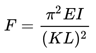
Where we see the effective length in the denominator, and the Modulus of Elasticity and Moment of Inertia of the section in the numerator. This tells us that the smaller the effective length of a section, as well as the higher the moment of inertia in the axis of analysis, will result in a higher critical load that would buckle the member.
Because most members aren’t fully symmetrical in all directions, members are usually analyzed in both principal directions of the section. In SkyCiv Structural 3D, the principal directions would be the Y and Z axis of a member, which corresponds to the vertical and horizontal axis of a section, respectively, when looking at it in plane view.
Do all members need to be checked for buckling?
Buckling is a very unique type of failure, and should not be forgotten or written off, but there are a few stipulations and general practices in the industry that allow engineers to disregard buckling as a failure method, only because that member would otherwise fail before it’s critical buckling stress is reached through a different failure method. These stipulations depend on the modulus of elasticity of the member, and therefore the material.
If a column is considered “long”, then it is susceptible to buckling and it should be checked. Otherwise, columns are considered “short” or “intermediate” in which case, buckling is less of a threat. The classification of members as short, intermediate, or long, is done by using the slenderness ratio that we calculated earlier.
For steel members, a slenderness ratio below 50 can be considered “short”. A slenderness ratio greater than 200 tells us the member is “long”, and buckling from compressive forces should be considered. Members with slenderness ratios between those two values are considered “intermediate”, where engineering judgment should be used.
For concrete members, the “short” and “long” designation cutoff occurs at a slenderness ratio of 10.
For wood members, buckling is more unique, since the material itself is not isotropic (the strength of the material varies). However, in most cases, wood members with a slenderness ratio below 10 can be considered “short”.
Overall, the check is fairly straightforward and quick, so most engineers air on the side of caution. Luckily, in SkyCiv Structural 3D, when users queue a buckling analysis, these checks are done for every single member at a fraction of the time.
Custom Member Restraints
Some of our new design modules have a feature called Restraints which will allow users to enter in dummy or pseudo restraints for more accurate design calculations. These are available on the AS4100 – 2020 and the AS 4600 – 2018 Design Modules.
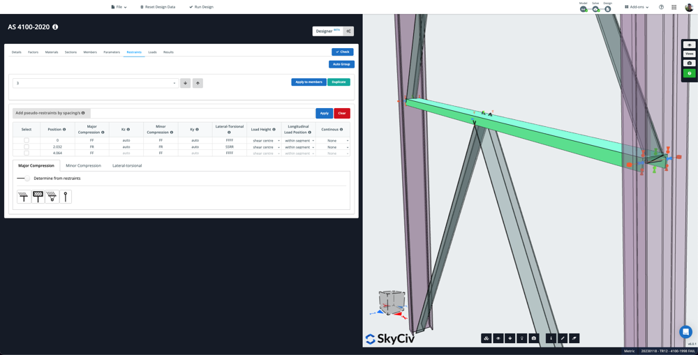
Each member is given a restraint id by default. Users can link similar members (same length, same section) with a single restraint ID to organise similar members and prevent multiple data entry. This can be done automatically using the Auto Group button – which will scan your model and assign similar members with the same restraint ID.
Adding Restraints
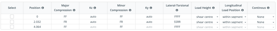
By default, the software will autodetect connection points and create a start/end and any intermediate restraints if they exist. In the above example, the single member is connected to two other members at the midpoint, so the restraint table shows a start/end and mid point restraint, with the relevant restraint codes (for instance, the below table it is fully restrained at the ends for Major Compression, but is free to rotate at the midpoint):
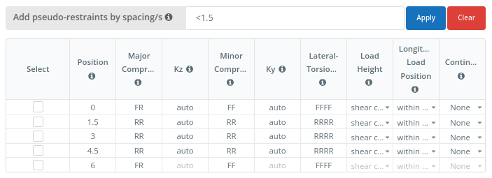
To add pseudo-restraints (restraints not being modelled), enter the spacing between them as a comma separated list. E.g. For a 6 m long member, 1.5,1.5,1.5 would add restraints at 1.5, 3, and 4.5. Alternatively, you can use the multiply operator to enter the same information. E.g. 3*1.5 would add 3 intermediate restraints with a 1.5 spacing (1.5, 3, 4.5). You can also use the < operator, which will add as many restraints as can fit along the member by reducing the start and end spacing. E.g <1.5 would also add restraints at 1.5, 3, 4.5
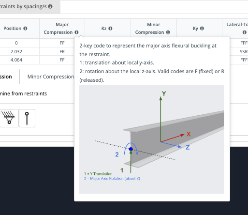
As with our Support and Member end fixity codes, F = Fixed and R = Released. For ease of use, clear and helpful info tips have been provided:
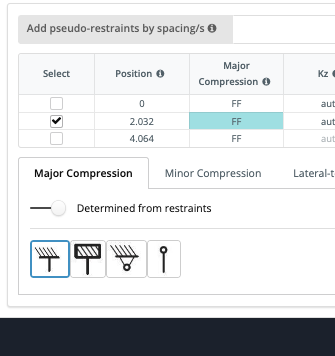
Finally, users can override or automatically update certain restraints with easy graphical representations. For instance, if I want to override the midpoint restraint with a full fixed restraint (in terms of major compression), I can tick on that restraint and click the fully fixed icon. The cell will change and highlight blue to reflect this change:
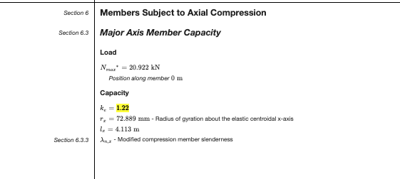
Finally, if I want to override the restraints completely, and not use those fixity codes, I can specify the Lz and Kz for the entire member, to be used for that calculation
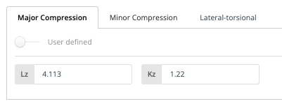
Reviewing the calculation report, we can see that is now being used in the calculations:
Example
Say you wish to restrain the top flange of a member if you wanted to restrain the top flange, I think you would a an “F” on the first input. You could add a restraint at that location, then under Lateral-Torsional Column you the code would be FRRR, indicating Fixed Top Flange Z and released in Bottom, Section Twist and Member Rotation (see below image). Or if you want to fully fix all those, you would enter FFFF.

(note the 4 values at the bottom left corner)
Continuous restraints can also be controlled by the last column Continuous where those restraints will be applied along the member until the next restraint point. So for instance, if you added a continuous restraint to the Top it would restrain the top flange from point 2 to point 3 in the below example. This will show graphically in the GUI:
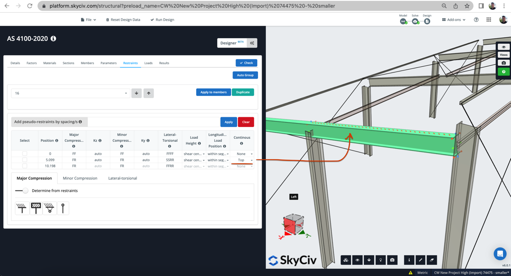
In this example, the member is full restrained in all directions (flanges, web and all) at the member start (x=0). There is then a midpoint partial lateral restraint (denoted by the SSRR), as it is continuous on the top flange, the partial restraint will continue from x = 5.099 to x =10.198.
SkyCiv Member Design Software
To learn more about all the features of SkyCiv Member Design Software, click the button below!