Using the SkyCiv Load Generator for Indian Standards (IS) 875 Part 3 2015 Wind Load Calculations
To calculate the wind load pressures for a structure using SkyCiv Load Generator, the process is to define first the code reference. From there, the workflow is to define the parameters in Project Tab, Site Tab, and Building Tab, respectively. However, free users can only use the calculation for a gable and open pitched/duopitched roof for a maximum of 3 solves per week. With a Professional Account or by purchasing the standalone Load Generator module, you can use all the features of this calculation as long as you want You can purchase the standalone module thru this link.
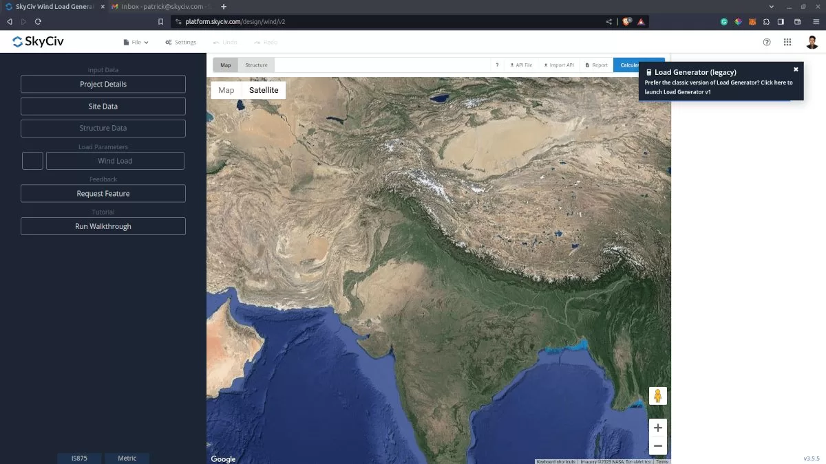
Figure 1. Load Generator UI for IS 875.
Site Data
Users can get the hourly wind pressure by location any time from the SkyCiv free wind speed map database. Using IS 875-3, you just need to put the Project Address and our software will automatically get the basic wind speed in our database. You can also override the this value to get a more appropriate design wind pressure.
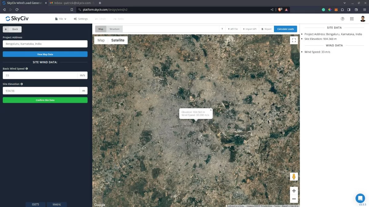
SkyCiv has digitalized the map as per the paperback standard. This means, you can simply enter in the site location and the software will automatically pull the wind speeds based on this input. The software will use our internal interpolator to calculate values between the contours, to ensure accurate wind speeds are used in your designs.
Site Input Parameters for Wind Load Calculation
Project Address – Used for getting the nearest wind speed based on the wind region and country
Basic Wind Speed – the basic wind speed to be used in calculating the design wind pressure. This is automatically determined based on Project Address located in India and can be modified by the user
Once the parameters above are completed, we can now proceed to the Structure Data section.
Structure Data
The structure data and the wind and snow parameters are separated into different sections. You need to define first the Structure you are analyzing. Currently, only Building structure is supported in IS 875-3.
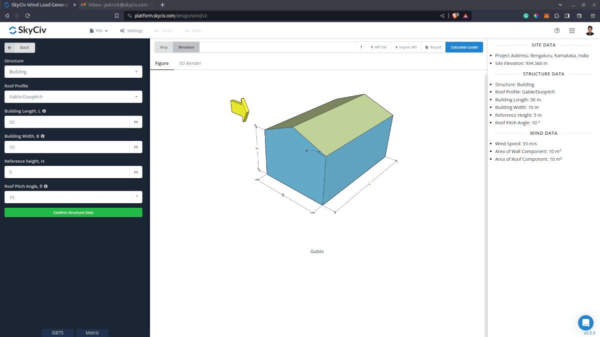
Figure 3. Structure data input for buildings..
For building structure, we need to fill the structure dimensions as shown in the building figure above. The option for the roof profiles are as follows:
- Gable/Duopich
- Monoslope/Monopitch
- Hip
- Open Monoslope
- Pitched
For free users, only Gable roof is available for Building. Once you have completed all the structure data inputs, you can visualize the structure by clicking the 3D Render at the right side.
Structure Input Parameters for Wind Load Calculation
Roof Profile – Used in pressure coefficient values based on the selected roof profile and roof pitch angle
Building Length – the dimension perpendicular to the wind direction as defined in IS 875-3. Used in calculation of pressure coefficients
Building Width – the dimension parallel to the wind direction as defined in IS 875-3. Used in calculation of pressure coefficients
Reference Height – the dimension of the structure from ground to the sloping roof.
Roof Pitch Angle – the roof slope in degree. Used in calculation of pressure coefficients
Once the parameters above are completed, we can now proceed to the Wind Load Parameters section.
Wind Data
To proceed with our wind load calculation, we need to check the checkbox first beside the Wind Load button. By default, this is checked when the site wind data has been defined.
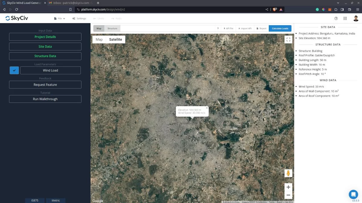
Figure 4. Checkbox for Wind Load Data.
The next step, is to define the Wind Source Direction the corresponding Terrain Category of the upwind area. The Wind Direction parameter is used in obtaining the upwind (left side) and downwind (right side) ground elevations to calculate for Topographic Factor, k3. In addition, the Terrain Category is used in determining the Terrain Roughness and Height Factor k2.
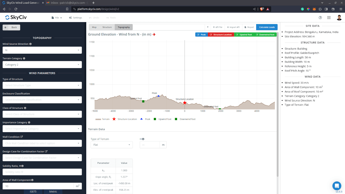
Figure 5. Elevation Data from Google Maps for upwind (left) and downwind side (right).
Topography Input Parameters
Wind Source Direction – used to obtain the elevation data on a specific direction section of the area. These elevation data are used in determining the Topographic Factor, k3
Type of Terrain – Options to select Flat, Hill, Escarpment, Ridge
Z – Height of obstruction/terrain. For type of terrain is set to option other than Flat terrain, this is used in calculating the Topographic Factor, k3
Lu – Horizontal distance from upwind base of the obstruction to its peak. For type of terrain is set to option other than Flat terrain, this is used in calculating the Topographic Factor, k3
Ld – Horizontal distance from peak of the obstruction to the downwind base. For type of terrain is set to option other than Flat terrain, this is used in calculating the Topographic Factor, k3
X – Horizontal distance of structure to the peak of the obstruction with the peak as the point of reference. For type of terrain is set to option other than Flat terrain, this is used in calculating the Topographic Factor, k3
H – Height of structure above ground. For type of terrain is set to option other than Flat terrain, this is used in calculating the Topographic Factor, k3
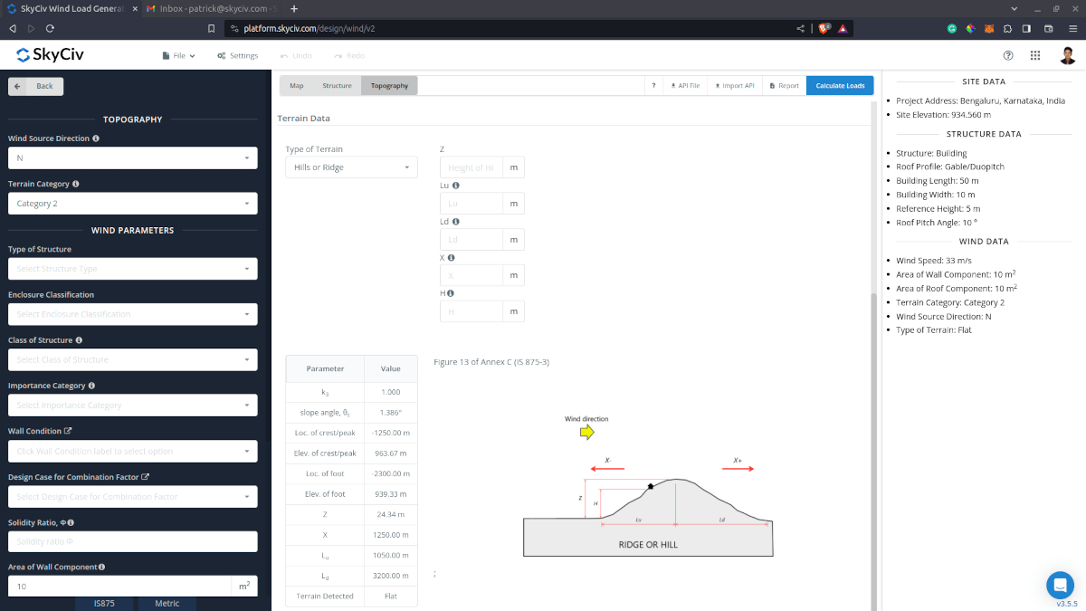
Figure 6. Topography Parameters for IS 875-3.
Wind Input Parameters for Building
Type of Structure – Required to be set to IS 875-3 Buildings
Enclosure Classification – Options are: With openings not more than 5% of the wall area but where there are no large openings; With medium openings between 5% and 20% of the wall area; and With large openings (larger than 20% of the wall area). Used in obtaining the internal pressure coefficients Cpi
Class of Structure – Used in determining Probability Factor, k1
Importance Category – Used in determining Importance Factor, k4
Wall Condition – For calculation of internal pressure coefficient Cpi for enclosed roof profiles. Can be defined by clicking the label to show the options.
Design Case for Combination Factor – For calculation of combination factor Kc. Can be defined by clicking the label to show the options.
Solidity Ratio – For calculation of net pressure coefficients Cpnet for open roof profiles
Floor Elevation – Since the wind pressure acting on the windward is parabolic in nature, this is used to approximate this pressure by assigning multiple rectangular pressure acting on the wall in between the level (for gable, hip, and monoslope roof)
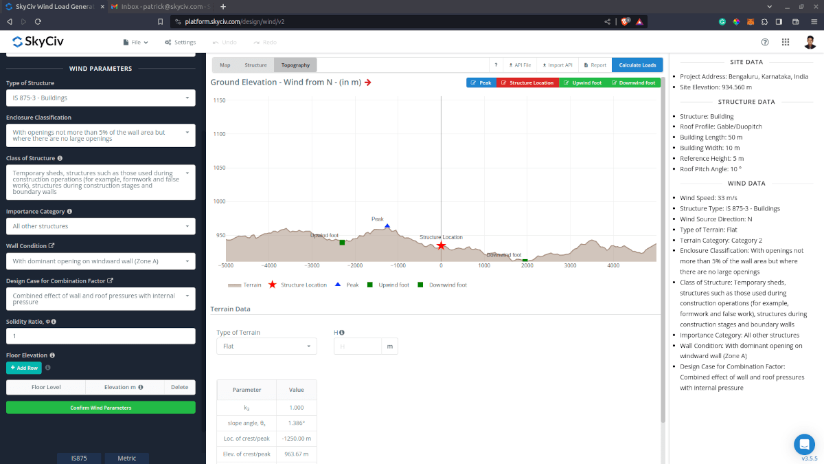
Figure 7. Wind Parameters for IS 875-3 Building.
Wind Input Parameters for Cladding
Type of Structure – Required to be set to IS 875-3 Buildings
Enclosure Classification – Options are: With openings not more than 5% of the wall area but where there are no large openings; With medium openings between 5% and 20% of the wall area; and With large openings (larger than 20% of the wall area). Used in obtaining the internal pressure coefficients Cpi
Class of Structure – Used in determining Probability Factor, k1
Importance Category – Used in determining Importance Factor, k4
Wall Condition – For calculation of internal pressure coefficient Cpi for enclosed roof profiles. Can be defined by clicking the label to show the options.
Design Case for Combination Factor – For calculation of combination factor Kc. Can be defined by clicking the label to show the options.
Solidity Ratio – For calculation of net pressure coefficients Cpnet for open roof profiles
Area of Wall Component – Can be a comma-separated value (i.e. 23,44,20) for multiple effective wind area. Used in calculating the design wind pressure for wall claddings or components
Area of Roof Component – Can be a comma-separated value (i.e. 23,44,20) for multiple effective wind area. Used in calculating the design wind pressure for roof claddings or components
Floor Elevation – Since the wind pressure acting on the windward is parabolic in nature, this is used to approximate this pressure by assigning multiple rectangular pressure acting on the wall in between the level (for gable, hip, and monoslope roof)
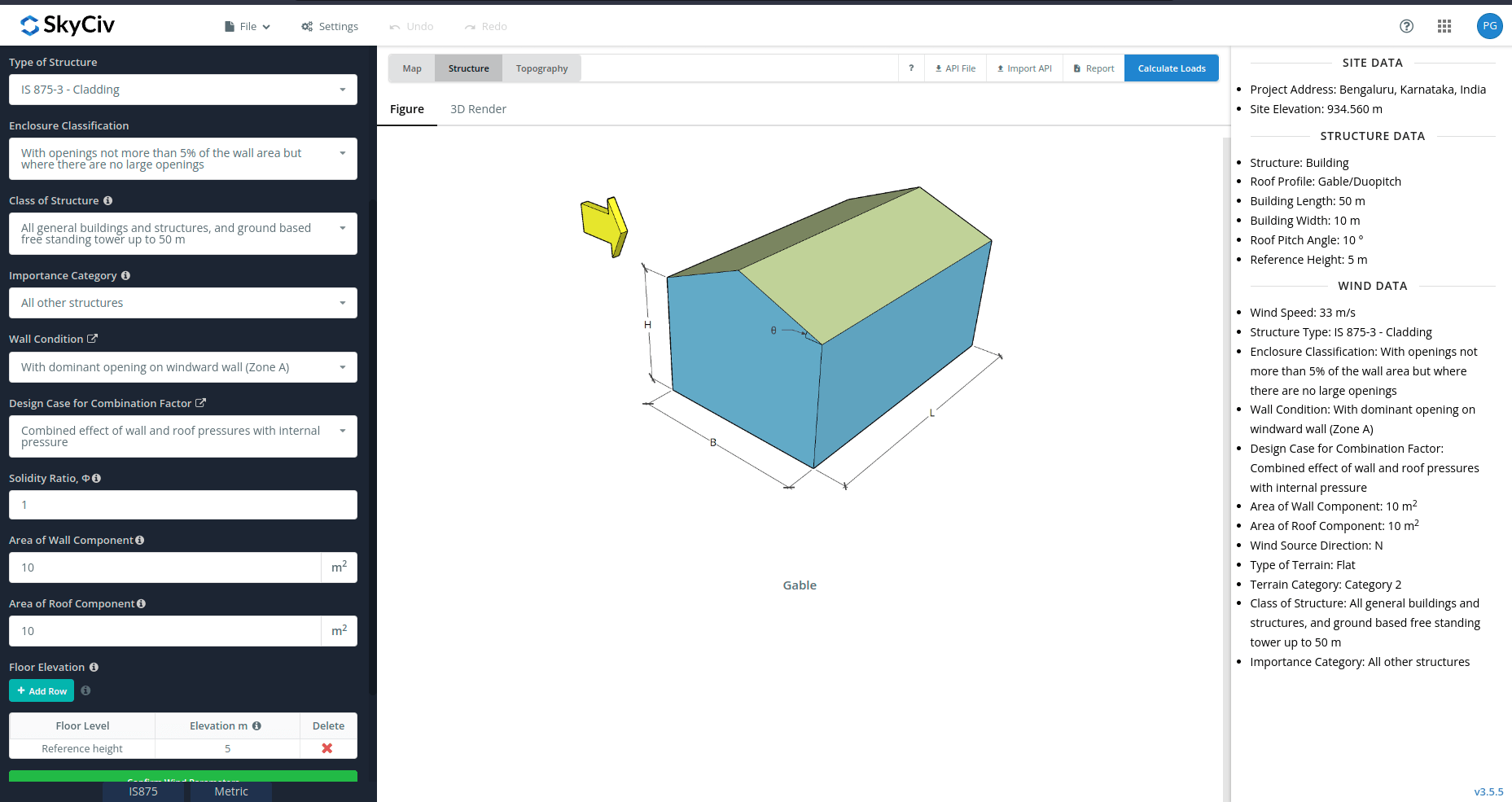
Figure 8. Wind Parameters for IS 875-3 Components/Cladding.
After all these parameters are defined, the next step is to click the Calculate Loads on the upper right side of the UI.
Results
The results of the calculation are shown as follows:
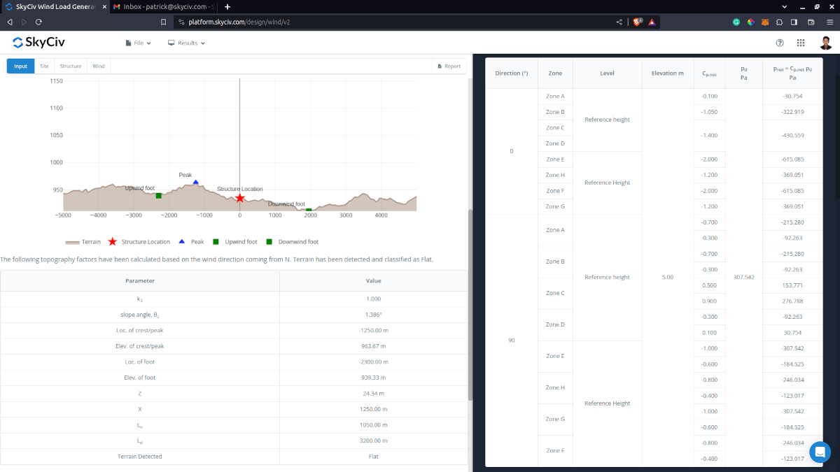
Figure 9. Wind pressure results for building using IS 875-3.
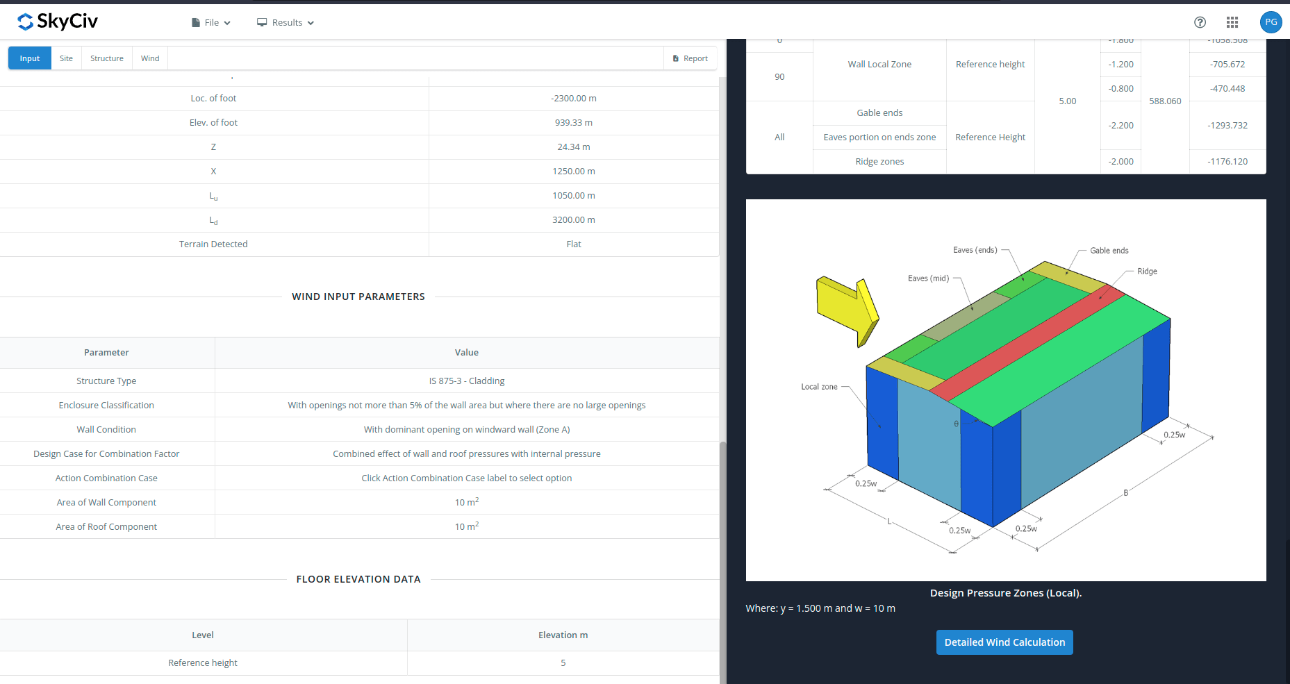
Figure 10. Wind pressure results for cladding using IS 875-3.
The summarized results are shown on the right side of the screen.
Detailed Calculation
The detailed wind load calculations can be accessed only by Professional account users and those who purchased the standalone load generator module. All the parameters and assumptions used in the calculation are displayed on the report to make it transparent to the user. You can download a sample detailed calculation thru the following links:
IS 875-3 Building
IS 875-3 Cladding
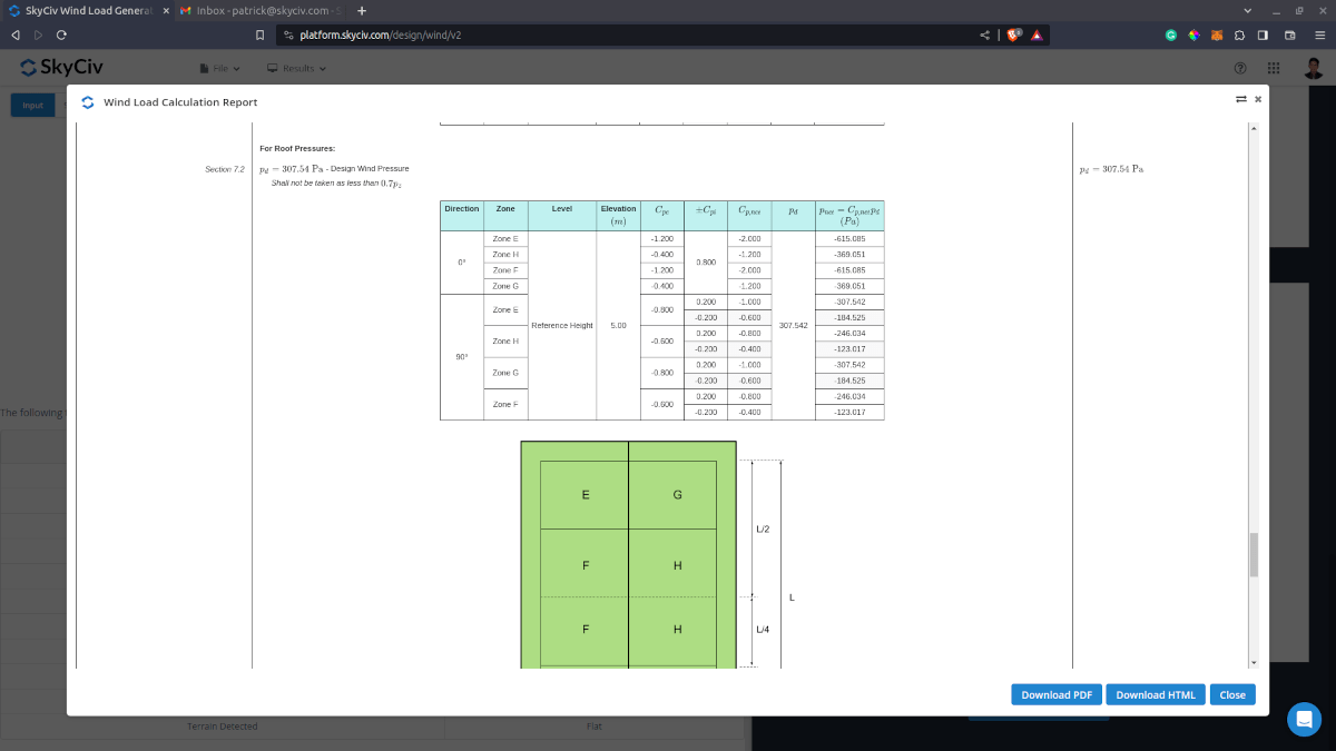
Figure 10. Detailed wind calculation.
For additional resources, you can use these links for reference: