Table of Contents
- Bending Moment Diagram Calculation
- Calculating Bending Moment Diagram by Hand
- Sign Convention for Bending Moment Diagrams
- How to Calculate Bending Using SkyCiv Beam
Bending Moment Diagram Calculation
Below are simple instructions on how to calculate the bending moment diagram of a simply supported beam. Study this method as it is very versatile (and can be adapted to many different types of problems. The ability to calculate the moment of a beam is a very common practice for structural engineers and often comes up in college and high school exams. It’s good to note early, that the SkyCiv Beam software can display these hand calculations instantly and automatically! We will follow todays tutorial with an example taken directly from the Hand Calculation Module in SkyCiv Beam.
Firstly, what is a bending moment? A moment is a rotational force that occurs when a force is applied perpendicularly to a point at a given distance away from that point. It is calculated as the perpendicular force multiplied by the distance from the point. A Bending Moment is simply the bend that occurs in a beam due to a moment.
It is important to remember two things when calculating bending moments; (1) the standard units are Nm and (2) when the top fiber is compressed, the bending is considered positive. With the definitions out of the way, let’s look at the steps to calculate a bending moment diagram!
Calculating Bending Moment Diagram by Hand
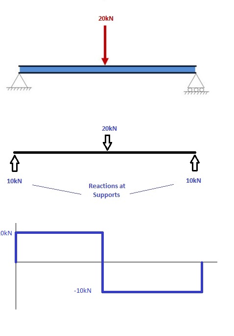
1. Calculate reactions at supports and draw Free Body Diagram (FBD)
If you’re not sure how to determine the reactions at the supports – please see this tutorial first. Once you have the reactions, draw your Free Body Diagram and Shear Force Diagram underneath the beam. Finally calculating the moments can be done in the following steps:
2. From left to right, make “cuts” before and after each reaction/load
To calculate the bending moment of a beam, we must work in the same way we did for the Shear Force Diagram. Starting at x = 0 we will move across the beam and calculate the bending moment at each point.
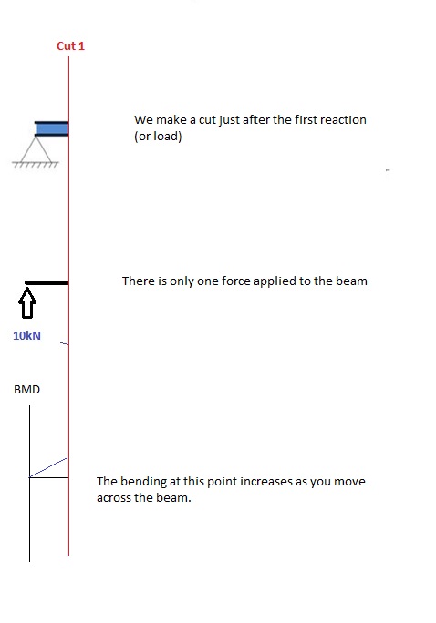
Cut 1
Make a “cut” just after the first reaction of the beam. In our simple example:
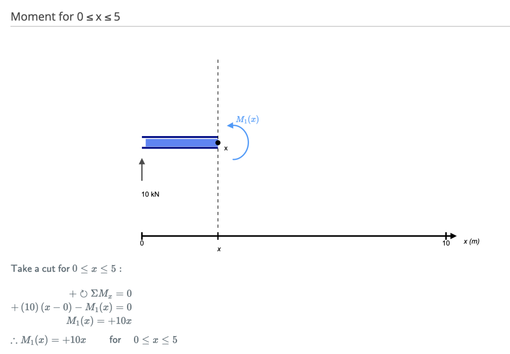
[Source: SkyCiv Beam Hand Calculation Module]
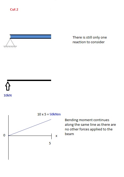
Cut 2
This cut is made just before the second force along the beam. Since there are no other loads applied between the first and second cut, the bending moment equation will remain the same. This means we can calculate the maximum bending moment (in this case at the midpoint, or x = 5) by simply substituting x=5 into the above equation:
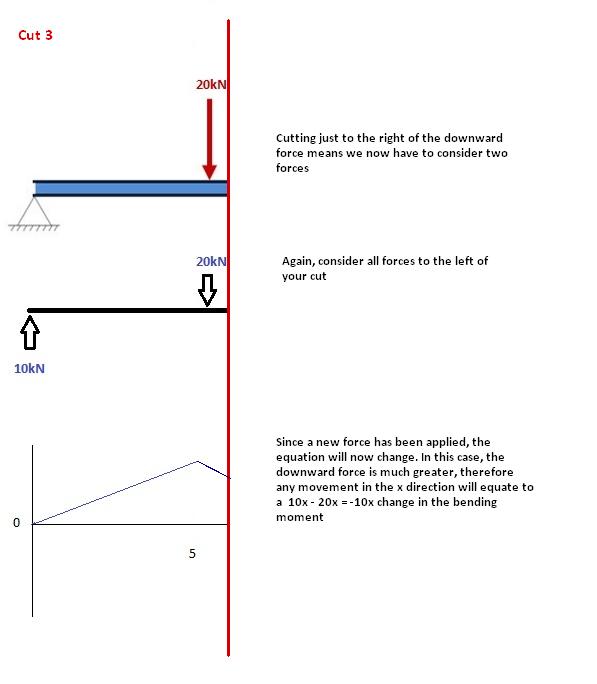
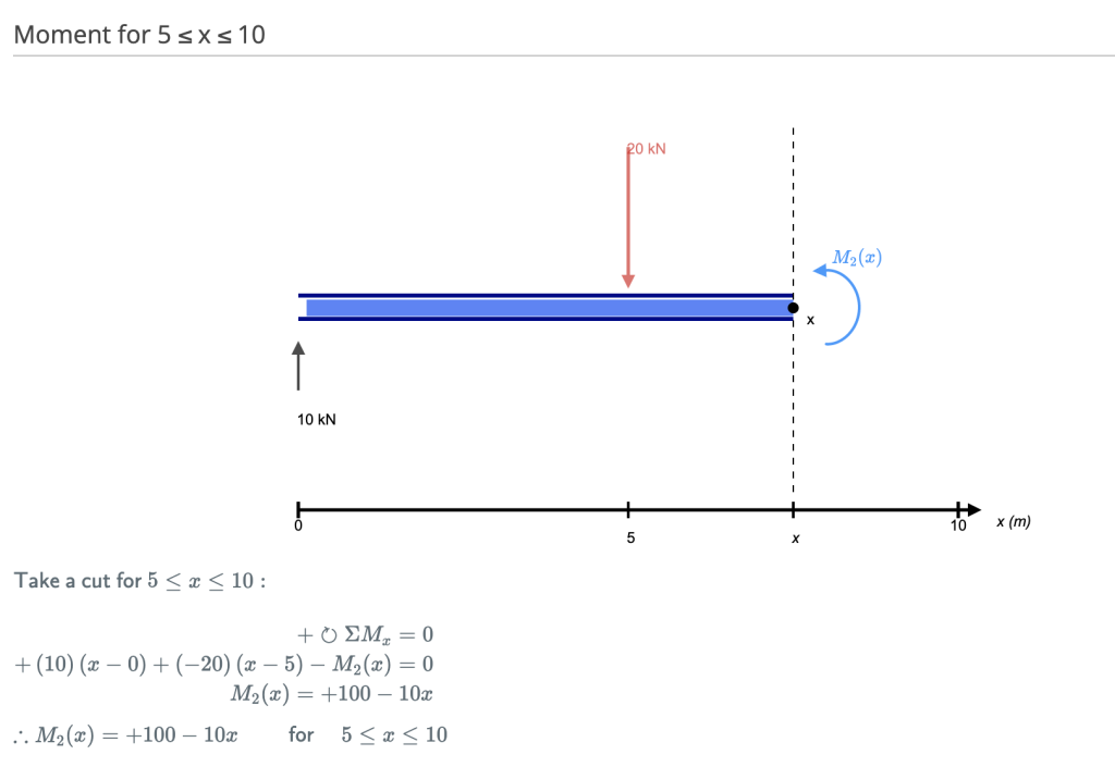
Cut 3
This cut is made just after the second force along the beam. Now we have TWO forces that act to the left of our cut: a 10kN support reaction and a -20kN downward acting load. So now we must consider both these forces as we progress along our beam. For every meter we move across the beam, there will a +10kNm moment added from the first force and -20kNm from the second.
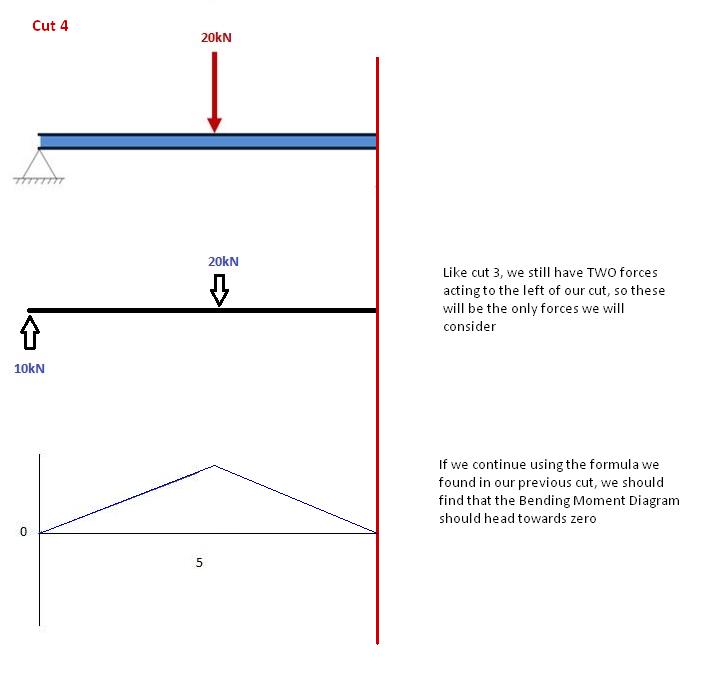
Cut 4
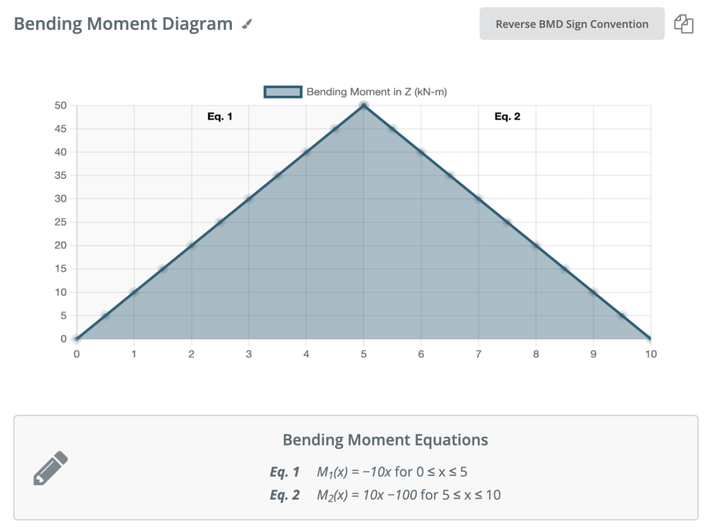
Again, let’s move across to the right of our beam and make a cut just before our next force. In this case, our next cut will occur just before the reaction from Right Support. Since there are no other forces between the support and our previous cut, the equation will remain the same: M(x) = 50 -10(x-5) for 5 ≤ x≤ 10 And let’s substitute x=10 into this to find the find bending moment at the end of the beam: M(x) = 50 – 10(10-5) = 0kNm This makes perfect sense. Since our beam is static (and no rotation) it makes sense that our beam should have zero moments at this point when we consider all our forces. It also satisfies one of our initial conditions, that the sum of moments at support is equal to zero. NOTE: If your calculations lead you to any other number other than 0, you have made a mistake!
Sign Convention for Bending Moment Diagrams
We’ve discussed how to find bending moment above. Bending Moment Diagrams can get somewhat confusing when it comes to sign conventions. You might see the same diagram drawn in opposite directions depending on the source. The sign convention used by SkyCiv is displayed below.
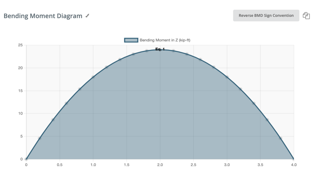
Positive Bending moment:
If the bending moment is positive, the top fiber of the beam is compressed.
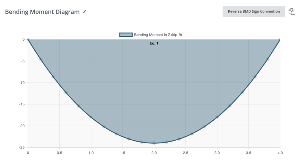
Negative Bending moment:
If the bending moment is negative, the bottom fiber of the beam is compressed.
That has been a guide to calculating bending moment diagrams, if you want to find out more about this topic, visit our Beam Tutorials page. Here you can find many other helpful tutorials such as bending stress formula or determine the reactions at the supports.
BONUS: Find bending moment with SkyCiv Beam
Under our paid version of SkyCiv Beam the calculator will show you the full hand calculations and the steps taken to hand calculate your bending moment diagrams. Simply model your beam using the calculator, and hit solve. It will show you the step-by-step calculations of how to draw a bending moment diagram (including cuts).
SkyCiv also has a Free Beam Calculator for those who would like to try the software before committing to the paid version. It calculates reactions at supports, shear force diagrams, and deflection and span ratios. So check it out now or sign up today to get started with SkyCiv Beam!
Otherwise, if you’re looking to calculate the bending moment capacity for an I-beam, try our I-Beam Load Calculator!