What Member Fixities mean and how they are identified in Structural 3D
Member End Fixities control how members are connected to each other or to the end nodes and include conditions such as a fixed, pinned, or spring connection.
Member-end fixity codes accept ‘F’ (Fixed), ‘R’ (Released) and ‘S’ (Spring) values. This code refers to the member end’s connection to its end node for each of the 6 degrees of freedom in the following order:
- Local x-axis Translation
- Local y-axis Translation
- Local z-axis Translation
- Local x-axis Rotation
- Local y-axis Rotation
- Local z-axis Rotation
NOTE: Member-end fixities are with respect to the member’s local axis system rather than the global axis system.
Fixed members have a fully fixed, rigid connection specified by a fixity code of ‘FFFFFF’.
Pinned members have a hinged connection denoted by a code of ‘FFFFRR’.
Spring members have a semi-rigid connection allowing partial flexibility denoted by a code of ‘FFFFSS’.
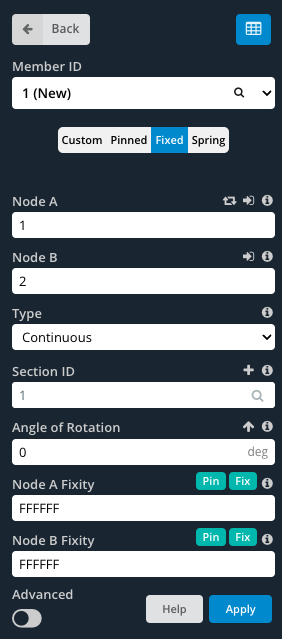
To specify custom values, ensure that the Custom button is selected. This enables the end fixity fields to be edited.
How to tell Member End Fixity while looking in the model space
When modeling with members, it is convenient to know the members’ end fixity without having to click on each member individually. By default, when members are modeled they have fully fixed end fixities (FFFFFF). The member looks like a single line between nodes:

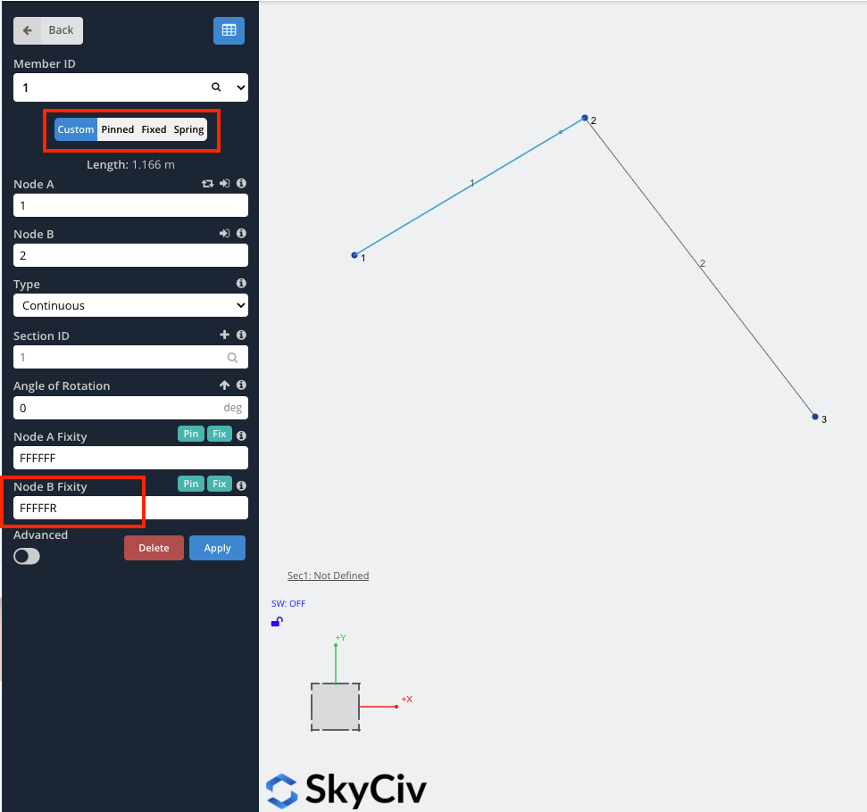
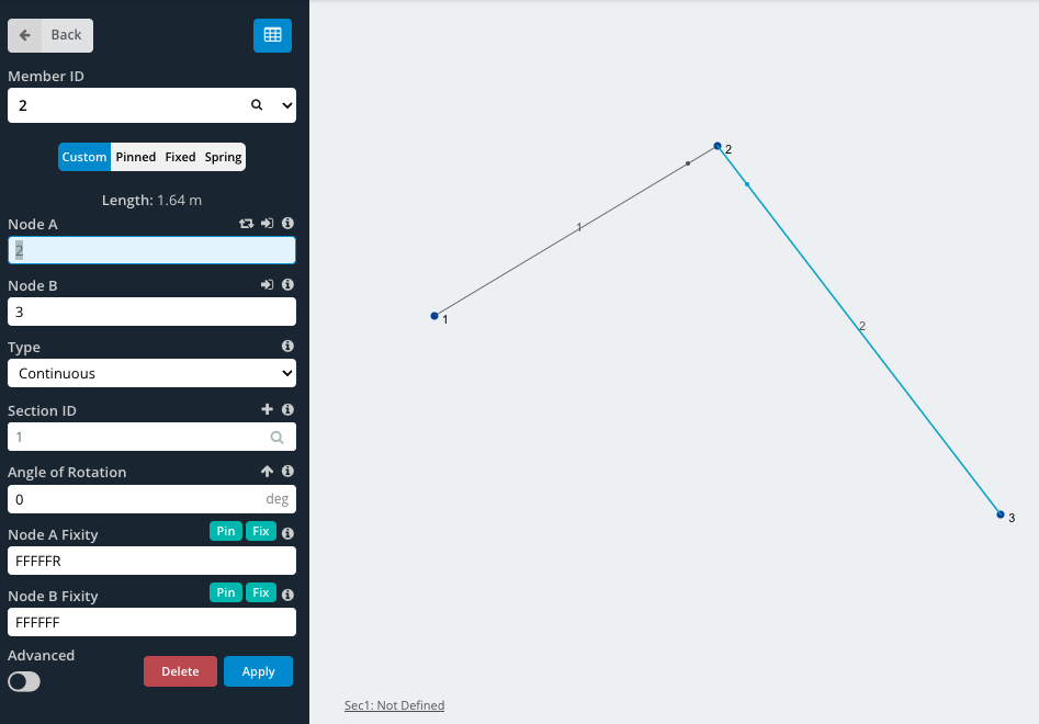
When any of the degrees of freedom are released, the member will have a small dot near the end of the member (as shown below circled in red). For example, for members with pinned end fixities (FFFRRR), the member would look like this:

Further Explanation
For more information on member fixities, SkyCiv has a technical article (including a video) in our blog, focussing on how to model member fixities:
Example: How to model pin connections or hinges
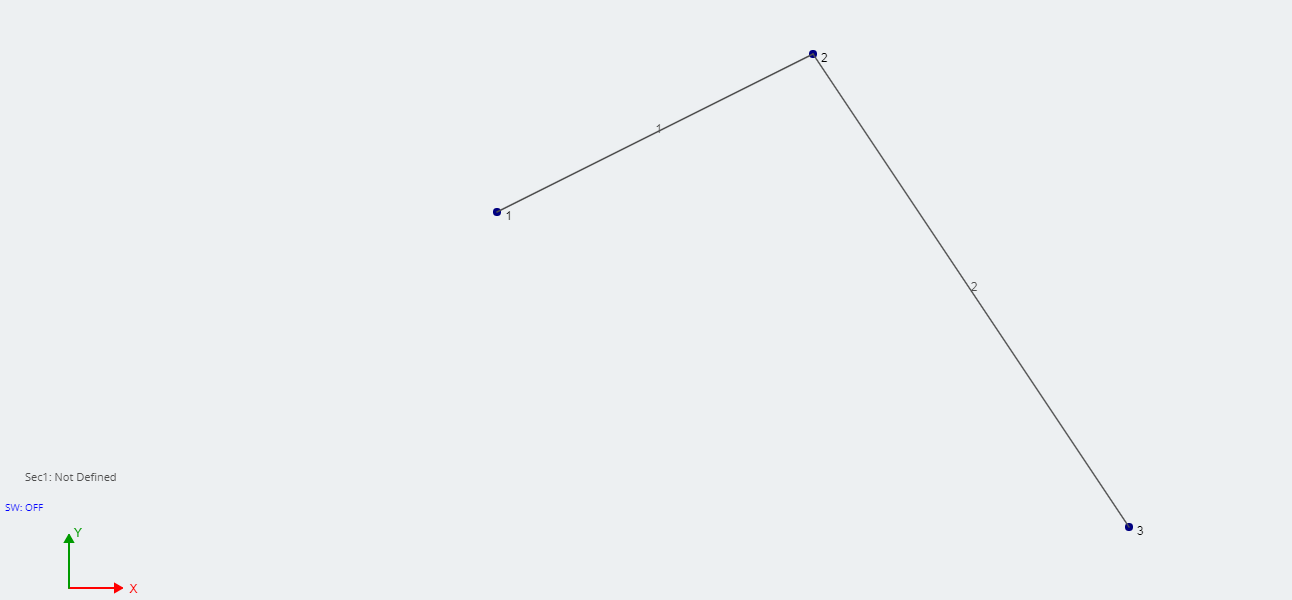
In this example, we will create a simple pin connection, such as a hinge. Start by creating 3 nodes and joining them with 2 members. In this example node, 2 will be the hinge.
More Information
For more information, SkyCiv has a further explanation on how to model a hinge, using Structural Analysis Software.