What is a Hinge Joint?
Firstly, what is a hinge joint? A hinge connection allows two members to rotate around their connection. At the hinge, both members are able to rotate freely with no restraint. Take the following diagram:
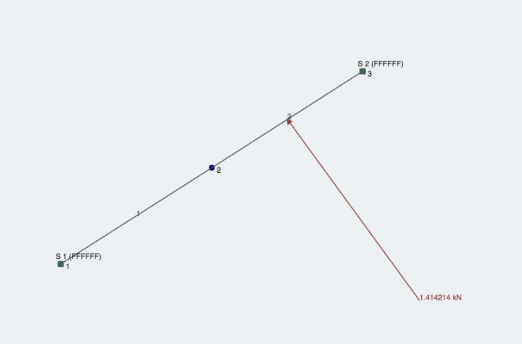
 An example of a moving hinge joint/connection
You can see how the second member is free to rotate under an applied load. The member is not transferring any bending moment to the other member. This is proven by the fact that there is 0 bending moment at the connecting node, meaning that there is no restraint against bending moment.
Understanding a Hinge Connection
The best way to fully comprehend how connections work is understand how the nodes are connected to the member ends. If it has a fixed degree of freedom, then the member is welded to the node - where the node goes, the member goes! Take the following two members:
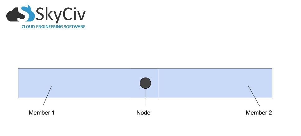
We can see they are joined by a common node. Now let's seperate the members to take a closer look:
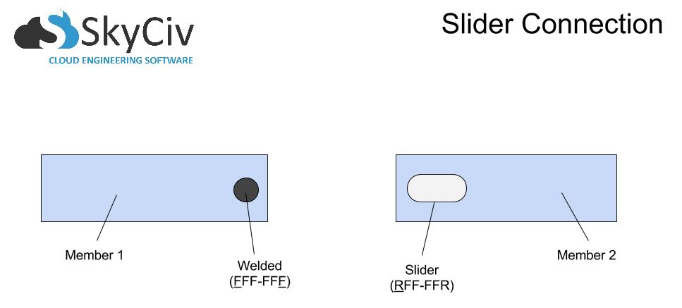
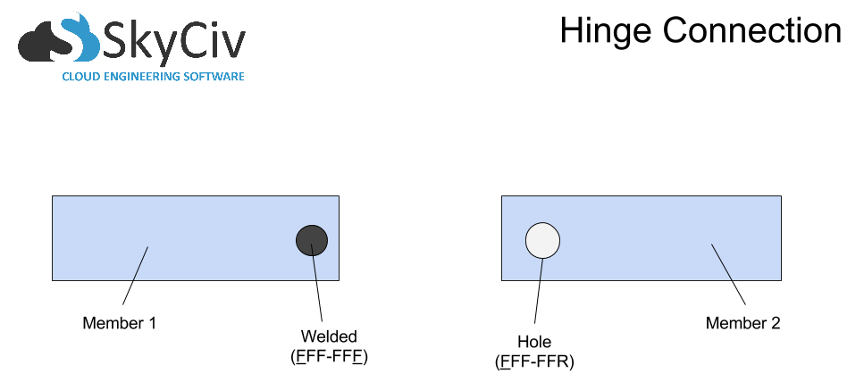
On the left, we have Member 1, fixed to the node with a restraint code of FFF-FFF. On the right, we have Member 2, which for this example has a whole cut out of it that allows the node to slide along the X and rotate about the Z. This is denoted by RFF-FFR. I have chosen this example because it is easy to understand and visualize the movement along the X-axis. This is an example of a hinge joint that can translate in the X. If you want to restrict the movement along the local x-axis, simply model the following connection:
How to Model the Hinge Joint
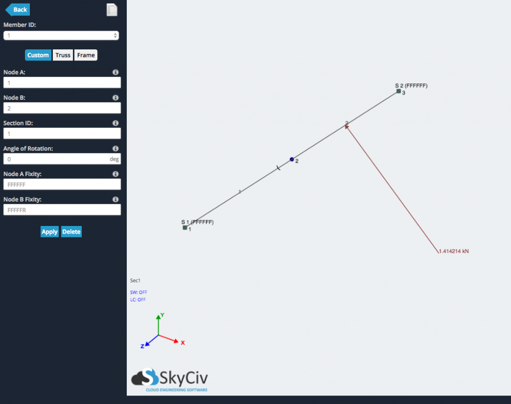
Once we understand our end fixities, it's time to model this in the software. Take a simple connection between two members:
To change this connection (node 2 in the diagram) to a hinge joint, we just need to change one of the member fixities to being FFF-FFR (as seen below). We can see Member 1's end is denoted by 'FFFFFR' in the left input menu. In doing this, we should see a little 'dash' added to the diagram, denoting that the member is no longer a fixed connection:
After we analyze the structure, we can check to see whether there is any bending moment force at the connection. Since the bending force is not being transferred between members, there should be 0 bending moment at the node where a hinge exists:
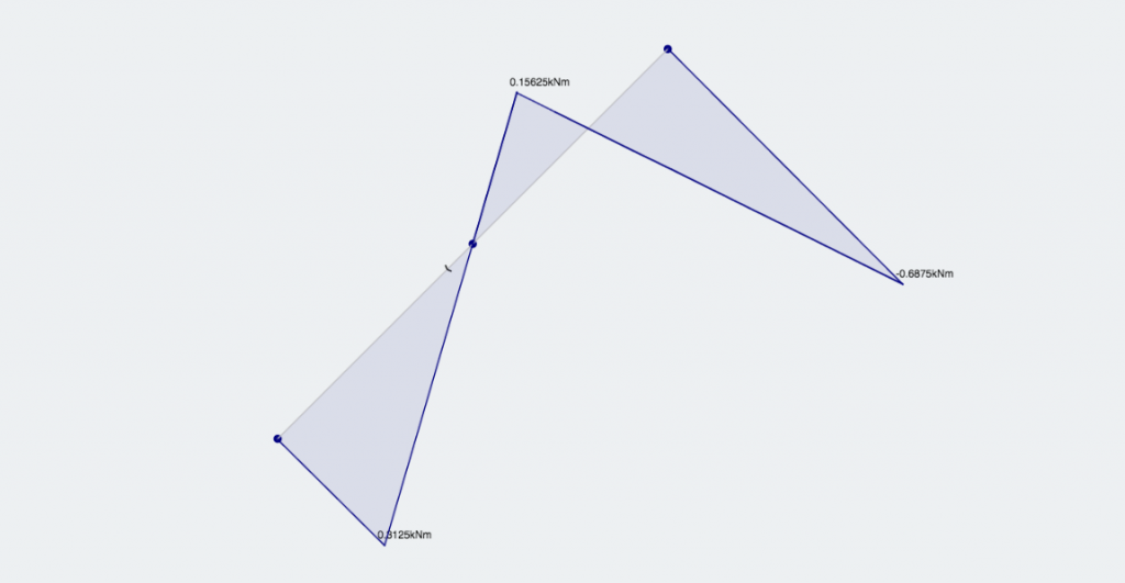
Bending Moment Force should be 0 at a hinge connection

CEO and Co-Founder of SkyCiv
BEng (Civil), BCom