An example of ASCE 7-16 wind load calculations (directional procedure) for an L-shaped building
In this article, an example wind load pressure calculation for an L-shaped building in Cordova, Tennessee will be shown. This calculation will be in accordance with ASCE 7-16 wind load calculations (directional procedure).
For this case study, the structure data are as follows:

| Location | Cordova, Memphis, Tennessee Elevation +110.0m |
| Occupancy | Miscellaneous – Plant Structure |
| Terrain | Flat farmland |
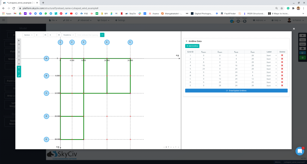
| Dimensions | 28m (12m width) x 24m (8m width) in plan Eave height of 5 m Apex height at elev. 8 m Roof slope: 1:2 for main frame (26.57°) 3:4 for extension (36.87°) With opening |
A similar calculation for a gable roof construction using ASCE 7-10 (imperial units) is referenced in this example and can be accessed using this link. The formula in determining the design wind pressure are:
For enclosed and partially enclosed buildings:
\(p = qG{C}_{p} -{q}_{i}({GC}_{pi})\) (1)
For open buildings:
\(p = q{G}_{f}{C}_{p} -{q}({GC}_{pi})\) (2)
Where:
\(G\) = gust effect factor
\({C}_{p}\) = external pressure coefficient
\(({GC}_{pi})\)= internal pressure coefficient
\(q\) = velocity pressure, in Pa, given by the formula:
\(q = 0.613{K}_{z}{K}_{zt}{K}_{d}V^2\) (3)
\(q\) = \({q}_{h}\) for leeward walls, side walls, and roofs,evaluated at roof mean height, \(h\)
\(q\) = \({q}_{z}\) for windward walls, evaluated at height, \(z\)
\({q}_{i}\) = \({q}_{h}\) for negative internal pressure, \((-{GC}_{pi})\) evaluation and \({q}_{z}\) for positive internal pressure evaluation \((+{GC}_{pi})\) of partially enclosed buildings but can be taken as \({q}_{h}\) for conservative value.
\({K}_{z}\) = velocity pressure coefficient
\({K}_{zt}\)= topographic factor
\({K}_{d}\)= wind directionality factor
\(V\) = basic wind speed in m/s
Risk Category
The first thing in determining the design wind pressures is to classify the risk category of the structure, which is based on the use or occupancy of the structure. Since this example is a plant structure, the structure is classified as Risk Category IV. See Table 1.5-1 of ASCE 7-16 for more information about risk categories classification.
Basic Wind Speed, \(V\)
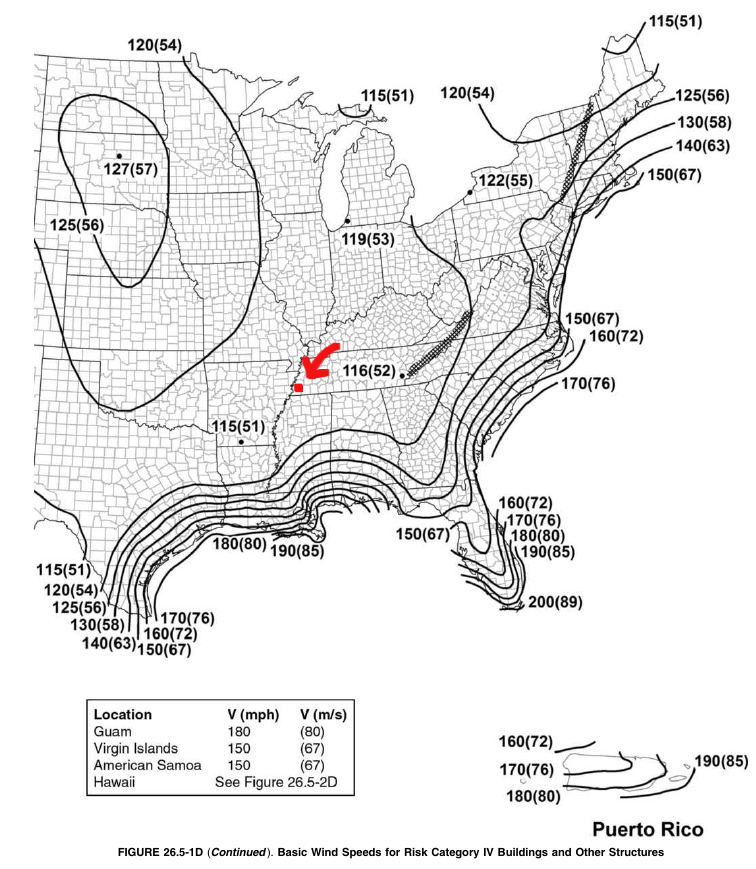
In ASCE 7-16, the wind speed data can be obtained from Figures 26.5-1 to 26.5-2. From Figure 26.5-1A, Cordova, Memphis, Tennessee is near the red dot shown in Figure 3 below, and subsequently, the basic wind speed, \(V\), is 52 m/s. Take note that the values should be interpolated between known wind contours.
SkyCiv can automate the wind speed calculations using just a few parameters. Try our SkyCiv Free Wind Tool.
Exposure Category
See Section 26.7 of ASCE 7-16 details the procedure in determining the exposure category.
Depending on the wind direction selected, the exposure of the structure shall be determined from the upwind 45° sector. The exposure to be adopted should be the one that will yield the highest wind load from the said direction. The description of each exposure classification is detailed in Section 26.7.2 and 26.7.3 of ASCE 7-16.
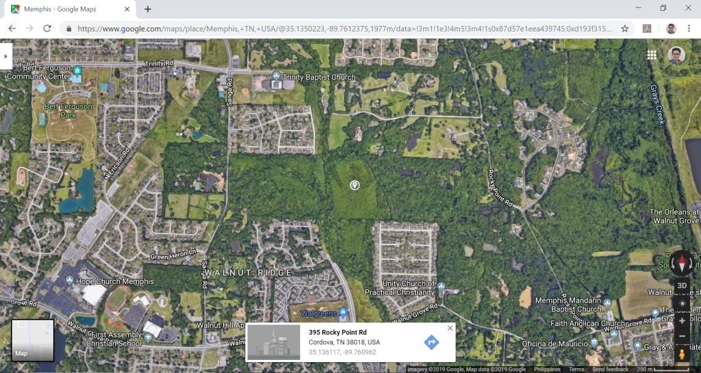
For our example, since the location of the structure is in a farmland in Cordova, Memphis, Tennessee, without any buildings taller than 30 ft, therefore the area is classified as Exposure C. A helpful tool in determining the exposure category is to view your potential site through a satellite image (Google Maps for example).
Wind Directionality Factor, \({K}_{d}\)
The wind directionality factors, \({K}_{d}\), for our structure are both equal to 0.85 since the building is the main wind force resisting system and also has components and cladding attached to the structure. This is shown in Table 26.6-1 of ASCE 7-16.
Topographic Factor, \({K}_{zt}\)
Since the location of the structure is in a flat farmland, we can assume that the topographic factor, \({K}_{zt}\), is 1.0. Otherwise, the factor can be solved using Figure 26.8-1 of ASCE 7-16. To determine if further calculations of the topographic factor are required, see Section 26.8.1, if your site does not meet all of the conditions listed, then the topographic factor can be taken as 1.0.
Note: Topography factors can automatically be calculated using SkyCiv Wind Design Software. For more information on calculation of topography factor, check this article.
Ground Elevation Factor, \({K}_{e}\)
The ground elevation factor, \({K}_{e}\), is introduced in ASCE 7-16 to consider the variation in the air density based on ground elevation above mean sea level. This factor can be calculated using:
\( {K}_{e} = {e}^{-0.000119{z}_{g}}\) (4)
Where:
\({z}_{g}\) is the ground elevation above mean sea level in meters
Hence, for this case study, since the ground elevation is +110.0m, \({K}_{e}\) is equal to 0.987.
Velocity Pressure Coefficient, \({K}_{z}\)
The velocity pressure coefficient, \({K}_{z}\), can be calculated using Table 26.10-1 of ASCE 7-16. This parameter depends on the height above ground level of the point where the wind pressure is considered, and the exposure category. Moreover, the values shown in the table is based on the following formula:
For 4.6 m < \({z}\) < \({z}_{g}\): \({K}_{z} = 2.01(z/{z}_{g})^{2/α}\) (5)
For \({z}\) < 4.6 m: \({K}_{z} = 2.01(4.6/{z}_{g})^{2/α}\) (6)
Where:
| Exposure | α | \({z}_{g}\)(m) |
| Exposure B | 7.0 | 365.76 |
| Exposure C | 9.5 | 274.32 |
| Exposure D | 11.5 | 213.36 |
Usually, velocity pressure coefficients at the mean roof height, \({K}_{h}\), and at each floor level, \({K}_{zi}\), are the values we would need in order to solve for the design wind pressures. For this example, since the wind pressure on the windward side is parabolic in nature, we can simplify this load by assuming that uniform pressure is applied on walls between floor levels. We can simplify the windward pressure and divide it into 2 levels, at the eave height (+5.0m), and at the mean roof height (+6.5m). Moreover, α = 9.5 and \({z}_{g}\) is equal to 274.32 m since the location of the structure is classified as Exposure C.
| Elevation (m) | \( {K}_{z} \) |
| 5 (eave height) | 0.865 |
| 6.5 (mean roof height) | 0.914 |
Velocity Pressure, \( q \)
From Equation (3), we can solve for the velocity pressure, \( q \) in Pa, at each elevation being considered.
| Elevation, m | \( {K}_{z} \) | \( {K}_{zt} \) | \( {K}_{d} \) | \( {K}_{e} \) | \( V \), m/s | \( q \), Pa |
| 5 (eave height) | 0.865 | 1.0 | 0.85 | 0.987 | 52 | 1202.87 |
| 6.5 (mean roof height) | 0.914 | 1.0 | 0.85 | 0.987 | 52 | \( {q}_{h} \) = 1271.01 |
Gust Effect Factor, \( G \)
The gust effect factor, \( G \), is set to 0.85 as the structure is assumed rigid (Section 26.11 of ASCE 7-16).
Enclosure Classification and Internal Pressure Coefficient, \( ({GC}_{pi}) \)
The plant structure is assumed to have openings that satisfy the definition of a partially enclosed building in Section 26.2 of ASCE 7-16. Thus, the internal pressure coefficient, \( ({GC}_{pi}) \), shall be +0.55 and -0.55 based on Table 26.13-1 of ASCE 7-16. Therefore:
\(+{p}_{i} = {q}_{i}(+G{C}_{pi}) \) = (1271.01)(+0.55) = 699.06 Pa
\(-{p}_{i} = {q}_{i}(-G{C}_{pi}) \) = (1271.01)(-0.55) = -699.06 Pa
External Pressure Coefficient, \({C}_{p}\)
For enclosed and partially enclosed buildings, the External Pressure Coefficient, \({C}_{p}\), is calculated using the information provided in Figure 27.4-1 through Figure 27.4-3. For a partially enclosed building with a gable roof, use Figure 27.4-1. External Pressure Coefficients for the walls and roof are calculated separately using the building parameters L, B and h, which are defined in Note 7 of Figure 27.4-1.
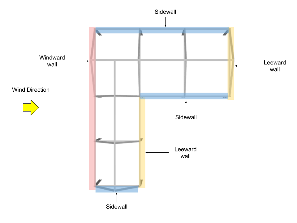
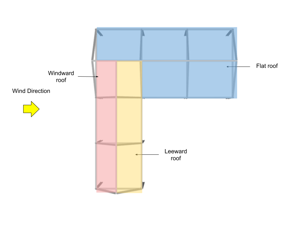
For this example, since the structure is asymmetric, four wind directions will be considered: two (2) for wind direction parallel to 24m side, and two (2) for wind direction parallel to 28m side.
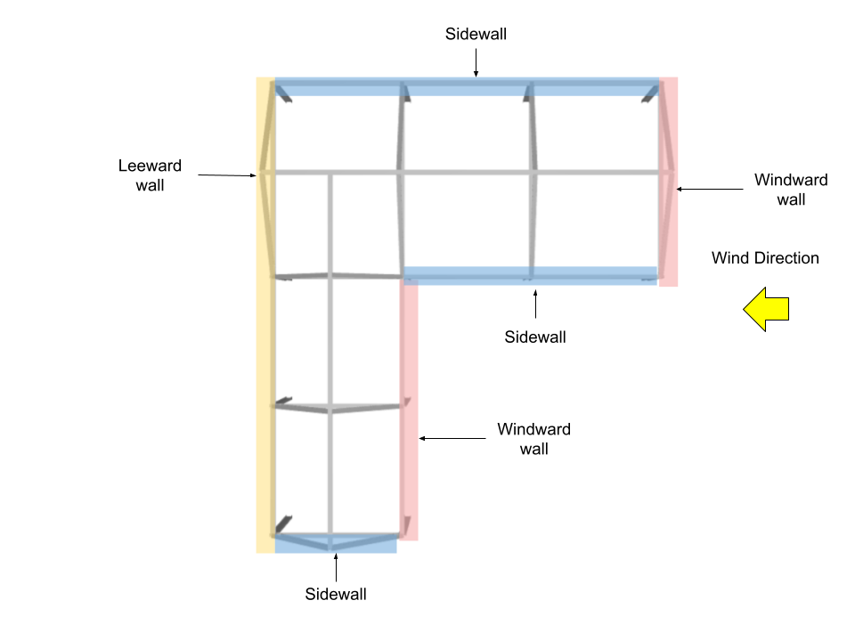
For Wind Direction parallel to 24m side
Thus, we need to calculate the L/B and h/L:
Roof mean height, h = 6.5 m
Building length, L = 24 m
Building width, B = 28 m
L/B = 0.857
h/L = 0.271
h/B = 0.232
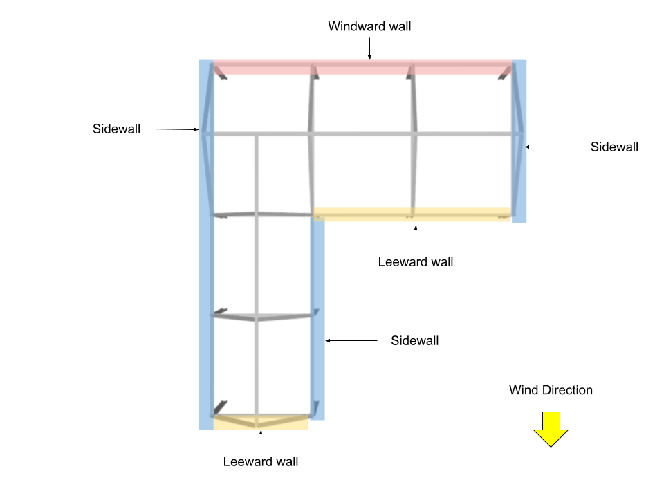
Wall Pressure Coefficients, \({C}_{p}\), and External Pressure, \({p}_{e}\)
.For walls, the external pressure coefficients are calculated from Figure 27.3-1 of ASCE 7-16 where \({q}_{h}\) = 1271.011 Pa and \( G \) = 0.85.
| Surface | h, m | Wall Pressure Coefficients, \({C}_{p}\) | \({p}_{e}\), Pa |
| Windward wall | 5.0 | 0.8 | 817.953 |
| 6.5 | 0.8 | 864.288 | |
| Leeward wall | 6.5 | -0.5 | -540.180 |
| Sidewalls | 6.5 | -0.7 | -756.252 |
Roof Pressure Coefficients, \({C}_{p}\), and External Pressure, \({p}_{e}\)
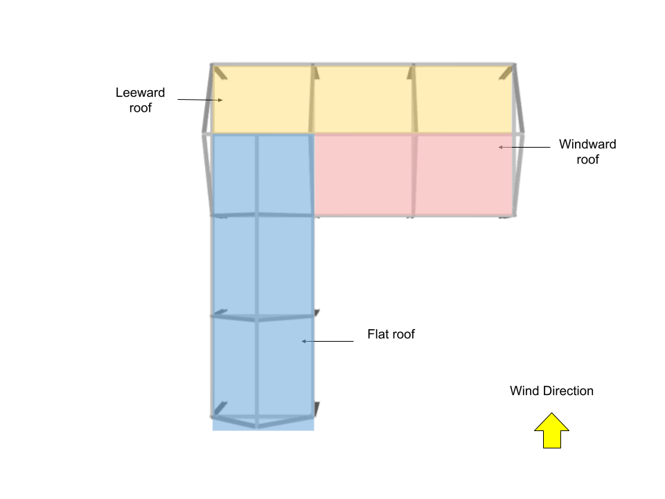
For roof, the external pressure coefficients are calculated from Figure 27.3-1 of ASCE 7-16 where \({q}_{h}\) = 1271.011 Pa. Note that for this wind direction, windward and leeward roof pressures (roof surfaces 1 and 2) are calculated using θ = 36.87° and θ = 0° for roof surfaces 3 and 4.
| Surface | Location | Roof Pressure Coefficients, \({C}_{p}\) | \({p}_{e}\), Pa |
| Windward roof | – | 0.4 | 432.144 |
| Leeward roof | – | -0.6 | -648.216 |
| Parallel to wind (along the ridge) | 0 to h from edge | -0.9 -0.18 |
-972.324 -194.465 |
| h to 2h from edge | -0.5 -0.18 |
-540.180 -194.465 |
|
| > 2h from edge | -0.3 -0.18 |
-324.108 -194.465 |
Therefore, combining \({p}_{e}\) and \({p}_{i}\), the corresponding design pressures can be obtained:
| Type | Surface | Elevation/Location, m | \({p}_{e}\), Pa | \({p}_{e}\) – +\({p}_{i}\), Pa | \({p}_{e}\) – -\({p}_{i}\), Pa |
| Walls | Windward wall | 5.0 | 817.953 | 118.897 | 1517.009 |
| 6.5 | 864.288 | 165.231 | 1563.344 | ||
| Leeward wall | – | -540.180 | -1239.236 | 158.876 | |
| Sidewalls | – | -756.252 | -1455.308 | -57.196 | |
| Roof | Windward | – | 432.144 | -266.912 | 1131.200 |
| Leeward | – | -648.216 | -1347.272 | 50.840 | |
| Flat (along ridge) | 0 to h | -972.324 -194.465 |
-1671.380 -893.521 |
-273.267 504.592 |
|
| h to 2h | -540.180 -194.465 |
-1239.236 -893.521 |
158.876 504.592 |
||
| > 2h | -324.108 -194.465 |
-1023.164 -893.521 |
374.948 504.592 |
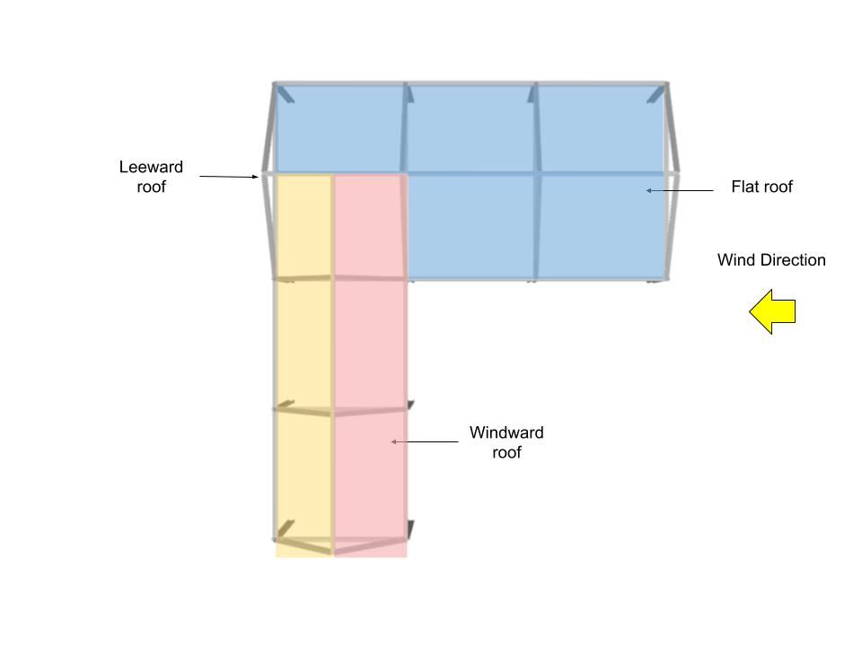
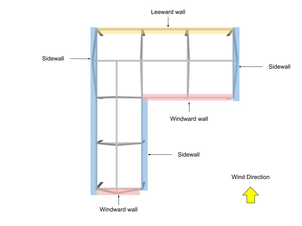
For Wind Direction parallel to 28m side
Thus, we need to calculate the L/B and h/L:
Roof mean height, h = 6.5 m
Building length, L = 28 m
Building width, B = 24 m
L/B = 0.857
h/L = 0.232
h/B = 0.271
Wall Pressure Coefficients, \({C}_{p}\), and External Pressure, \({p}_{e}\)
.For design wall pressure, the external pressure coefficients are calculated from Figure 27.3-1 of ASCE 7-16 where \({q}_{h}\) = 1271.011 Pa and \( G \) = 0.85.
| Surface | h, m | Wall Pressure Coefficients, \({C}_{p}\) | \({p}_{e}\), Pa |
| Windward wall | 5.0 | 0.8 | 817.953 |
| 6.5 | 0.8 | 864.288 | |
| Leeward wall | 6.5 | -0.467 | -504.528 |
| Sidewalls | 6.5 | -0.7 | -756.252 |
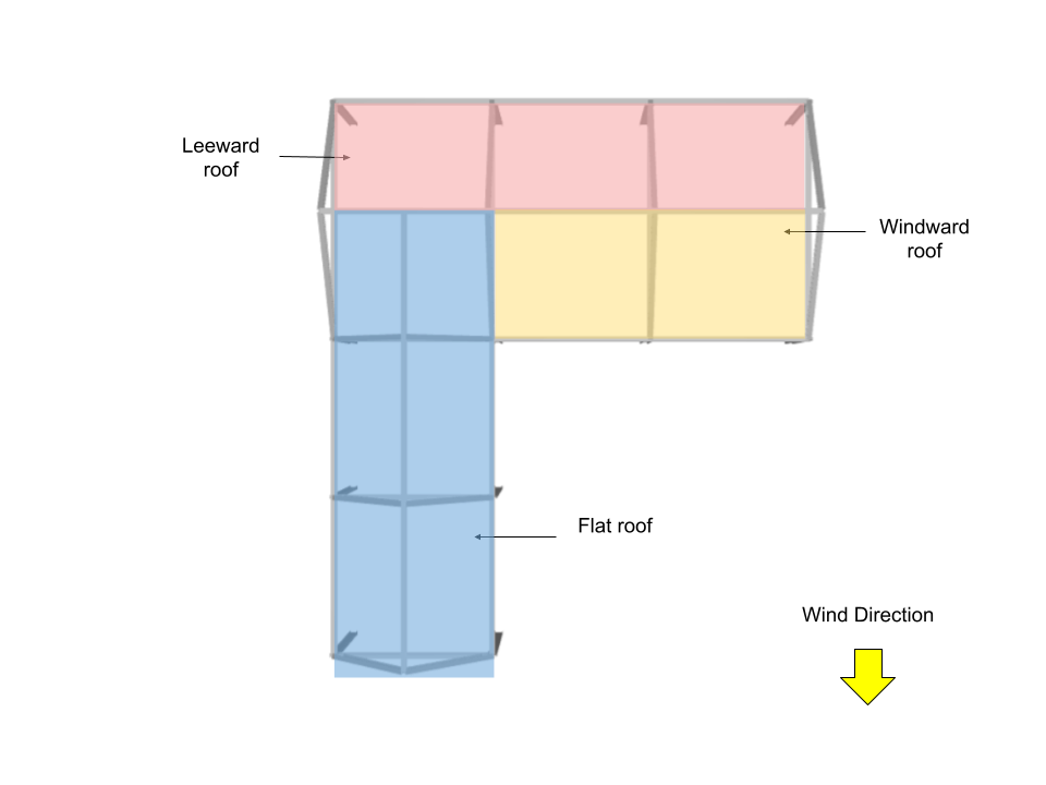
Roof Pressure Coefficients, \({C}_{p}\), and External Pressure, \({p}_{e}\)
For roof, the external pressure coefficients are calculated from Figure 27.3-1 of ASCE 7-16 where \({q}_{h}\) = 1271.011 Pa. Note that for this wind direction, windward and leeward roof pressures (roof surfaces 3 and 4) are calculated using θ =26.57° and θ = 0° for roof surfaces 1 and 2.
| Surface | Location | Roof Pressure Coefficients, \({C}_{p}\) | \({p}_{e}\), Pa |
| Windward roof | – | -0.2 0.3 |
-216.072 324.108 |
| Leeward roof | – | -0.6 | -648.216 |
| Parallel to wind (along the ridge) | 0 to h from edge | -0.9 -0.18 |
-972.324 -194.465 |
| h to 2h from edge | -0.5 -0.18 |
-540.180 -194.465 |
|
| > 2h from edge | -0.3 -0.18 |
-324.108 -194.465 |
Therefore, combining \({p}_{e}\) and \({p}_{i}\), the corresponding design pressures can be obtained:
| Type | Surface | Elevation/Location, m | \({p}_{e}\), Pa | \({p}_{e}\) – +\({p}_{i}\), Pa | \({p}_{e}\) – -\({p}_{i}\), Pa |
| Walls | Windward wall | 5.0 | 817.953 | 118.897 | 1517.009 |
| 6.5 | 864.288 | 165.231 | 1563.344 | ||
| Leeward wall | – | -504.528 | -1203.584 | 194.528 | |
| Sidewalls | – | -756.252 | -1455.308 | -57.196 | |
| Roof | Windward | – | -216.072 324.108 |
-915.128 -374.948 |
482.984 1023.164 |
| Leeward | – | -648.216 | -1347.272 | 50.840 | |
| Flat (along ridge) | 0 to h | -972.324 -194.465 |
-1671.380 -893.521 |
-273.267 504.592 |
|
| h to 2h | -540.180 -194.465 |
-1239.236 -893.521 |
158.876 504.592 |
||
| > 2h | -324.108 -194.465 |
-1023.164 -893.521 |
374.948 504.592 |

Structural Engineer, Product Development
MS Civil Engineering
References:
- Coulbourne, W. L., & Stafford, T. E. (2020, April). Wind Loads: Guide to the Wind Load Provisions of ASCE 7-16. American Society of Civil Engineers.
- American Society of Civil Engineers. (2017, June). Minimum design loads and associated criteria for buildings and other structures. American Society of Civil Engineers.