In structural engineering, the strength and stability of connections are of utmost importance to the overall performance of a structure. One critical aspect of connection design is the column splice connection, where the joining of two columns is a pivotal point. To ensure the integrity of such connections, engineers can turn to the American Institute of Steel Construction (AISC) 360-16 specification. However, with the advancement of technology, connection design software like SkyCiv offers a user-friendly alternative that simplifies the process and proves to be not only effective but also cost-efficient.
The Calculations Behind Column Splice Connections
Calculating the capacity of a column splice connection can be a complex task. However, AISC 360-16 provides engineers with a comprehensive guide that breaks down the intricate calculations into manageable steps. This specification outlines the procedures for determining the axial load-carrying capacity, moment capacity, and shear capacity of a column splice connection.
While manual calculations are a hallmark of traditional engineering practices, the digital age has ushered in new tools that can significantly expedite the design process. This is where connection design software like SkyCiv comes into play. SkyCiv’s intuitive interface allows engineers to input column information, plate sizes, bolt specifications, and loading conditions with ease. With SkyCiv’s column splice calculator, designing column splice connections becomes a streamlined process that empowers engineers to focus on the design itself rather than the calculations.
SkyCiv: A Game-Changer in Connection Design
What sets SkyCiv apart from its competitors is not just its user-friendly interface, but also its affordability. In a world where engineering software costs can add up quickly, SkyCiv offers a cost-effective solution that doesn’t compromise on quality. Whether you’re a seasoned professional or a budding engineer, SkyCiv’s pricing model ensures that connection design becomes accessible to all.
Bolting or Welding: Choosing the Right Connection Method
When it comes to column splice connections, the choice between bolting and welding can significantly impact the design. While both methods have their merits, bolting is the more commonly preferred option due to its versatility and ease of implementation. Bolts offer the advantage of being adjustable and replaceable, which is essential in scenarios where adjustments or modifications might be necessary.
Preparing the Column Contact Surface: The “Fit to Bear” Approach
One fascinating technique that engineers often employ to optimize column splice connections is preparing the column contact surface for a “fit to bear” condition. This involves ensuring that the contact surfaces of the columns are properly aligned and in full contact. By doing so, the compressive forces are transferred through bearing rather than relying solely on the bolts. This not only enhances the structural integrity of the connection but also adds an element of cost-effectiveness to the design.
The Need for Column Splice Connections
Column splice connections play a crucial role in scenarios where columns need to be extended, replaced, or connected for various reasons. These scenarios arise when the height of a structure exceeds the standard length of available columns, or when retrofitting is required due to design changes, modifications, or expansion. In such cases, well-designed and executed column splice connections are essential to maintaining the stability and safety of the structure.
Now onto using SkyCiv software.
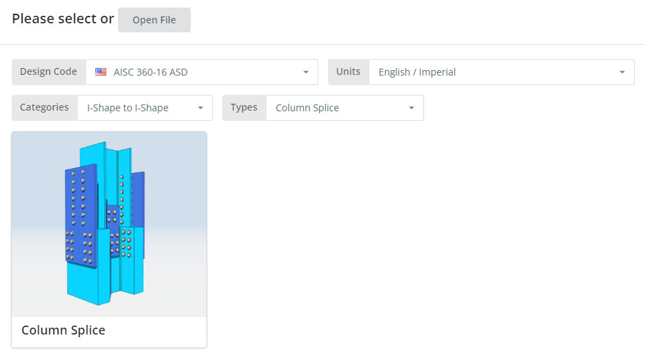
The Design Code can be AISC 360-16 ASD or LRFD. Units can be English/Imperial or SI/Metric. Now click the “Column Splice” tile.
Project Tab
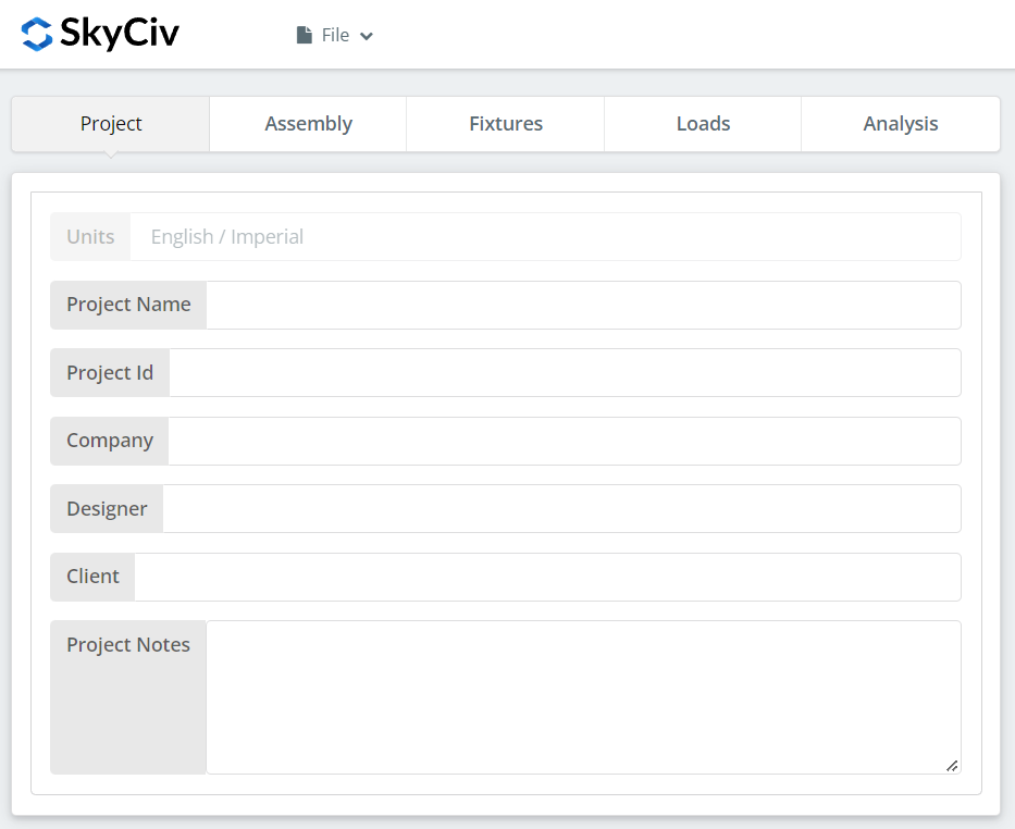
Here you can specify the details of the project you are currently working.
Assembly Tab
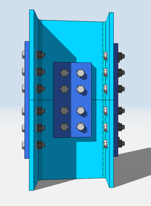
There are three tabs under Assembly. This is where you specify the Lower Column, Upper Column, and Connection (Flange Plate and Web Plate) properties.
Lower Column Tab

Here you can specify the section/shape of the lower column and its material grade. You can either choose A992 or A36 material. But if you are using a different material, you can choose Custom and manually input the Fy and Fu values.
Upper Column Tab
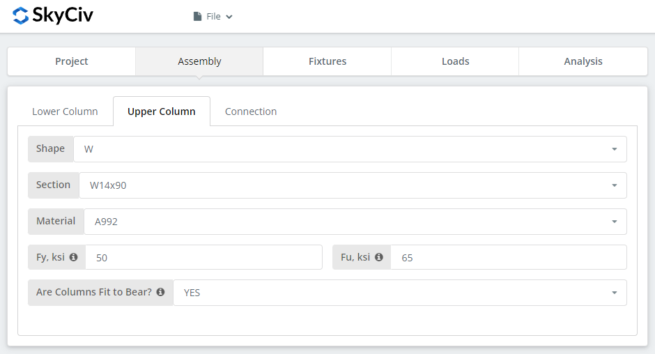
Similar inputs with the lower column tab but with an addition to specify if the columns are fit to bear or not. If you select “YES”, this means the compressive load will be designed at the column contact surface instead of the bolted connection, which effectively will result to a more economical design but you also need to make sure to communicate to your fabricator that the columns are properly prepared as fit to bear.
Connection Tab – Flange Plate Button
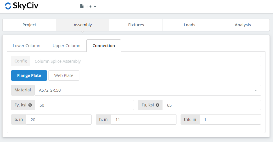
Here you can specify the properties of the flange plate. Material grade of A36, A992 or A572.GR50 but you can also specify “Custom” and manually input Fy and Fu. Set the b (width), h (height), and thk (thickness) of the plate. Now don’t forget to look closely at the 3D renderer and make sure the plate geometry make sense. Just make sure there is enough space for the bolts that will be set on the fixtures tab later.
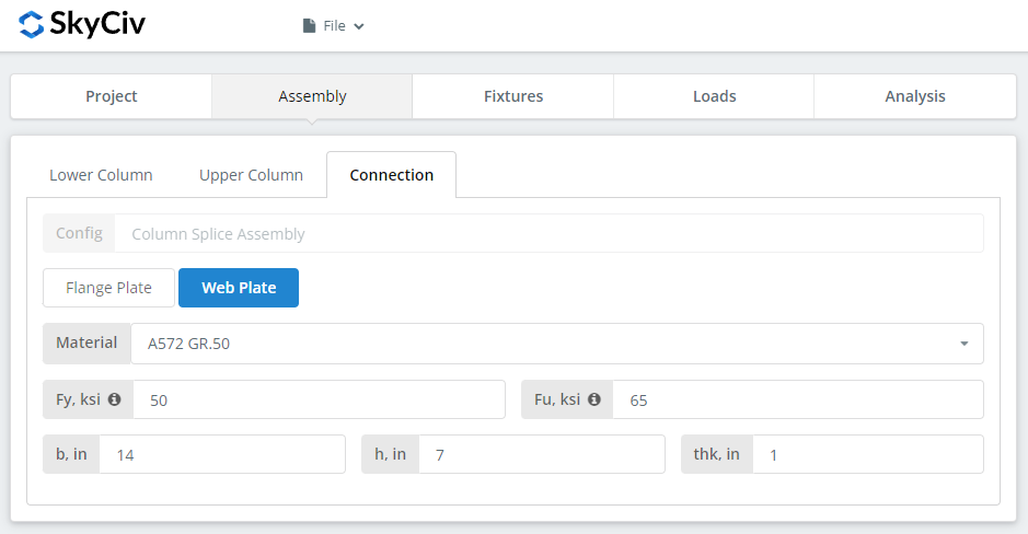
Connection Tab – Web Plate Button
Similar to the flange plate button inputs. And again, make sure the connection makes sense by looking at the 3D renderer. Take advantage of its functionality.
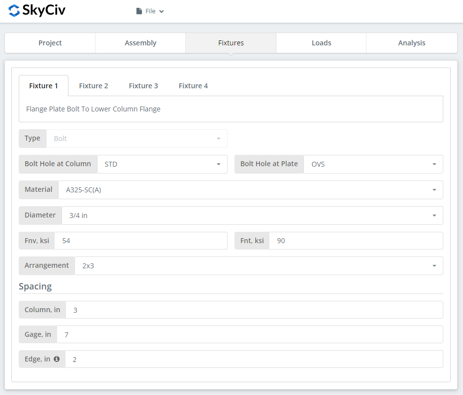
Fixture 1-4 Tab
Here is where you can specify the bolt information for the flange plate and web plate connections.
Fixture 1 – Flange plate to Lower Column Flange
Fixture 2 – Flange plate to Upper Column Flange
Fixture 3 – Web plate to Lower Column Web
Fixture 4 – Web plate to Upper Column Web
First, specify the bolt-hole types at the column flange/web and flange/web plates. Fabricators usually prefer using standard holes (STD) at member and oversized holes (OVS) at flange plate to allow better fitting at the field.
Next, select the bolt material or grade. You can choose either A307, A325, A490, or a Custom input. N or X bolts for bearing-type connections and SC for slip critical connections. Note that slip-critical connections generally have lesser bolt capacity. You should only use SC when there is a presumed slip in the direction of the force. In this specific example, if you use OVS holes at any of the beam or plate, the bolt will be automatically checked as slip critical. As for N versus X, X has a larger bolt shear capacity but you will have to make sure that bolt threads are excluded from the shear plane thus you will need to communicate this properly with the erector. And for SC(A) versus SC(B), SC(B) has a larger bolt capacity but you will also need a more thorough cleaning of the plies, for example, SSPC-SP6 or Commercial Blast Cleaning.
Next, specify the bolt diameter. You can choose from 5/8″ up to 1-1/2″ diameter or the equivalent metric units. Then, specify the bolt arrangement. You can choose up to 8 bolt rows and 12 bolt columns. Don’t forget to specify the bolt row spacing, bolt column spacing, and bolt gage as well. As for the “edge” input, this is the distance from the column end to the first bolt column.
Loads Tab
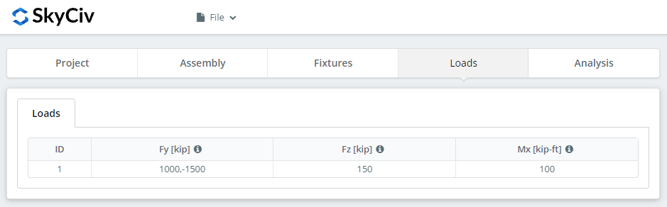
Don’t forget to input the compressive/tensile load ‘Fy’, horizontal shear load under ‘Fz’, and strong axis moment load under ‘Mx’. Hover over the tooltips to get a better idea on the direction of these loads.
Analysis Tab
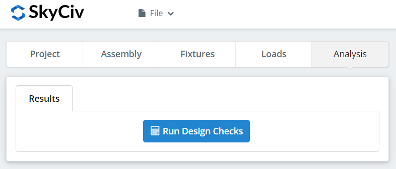
And finally, click “Run Design Checks”. If you missed any needed inputs on the previous tabs, this will notify you to fill in the missing inputs.
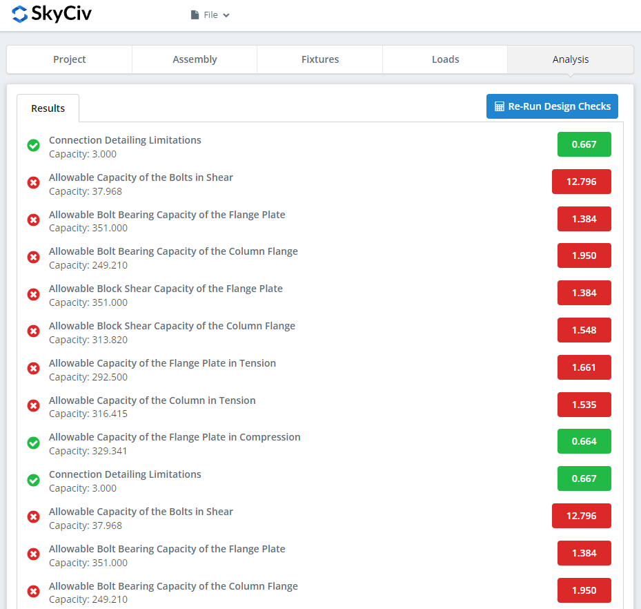
After clicking “Run Design Checks”, you can see a summary if your connection failed or not. If it failed, manually change the inputs in the previous tabs and then, click “Re-Run Design Checks”. When it’s finally okay, click “Get Calculation Report” to see the detailed report.
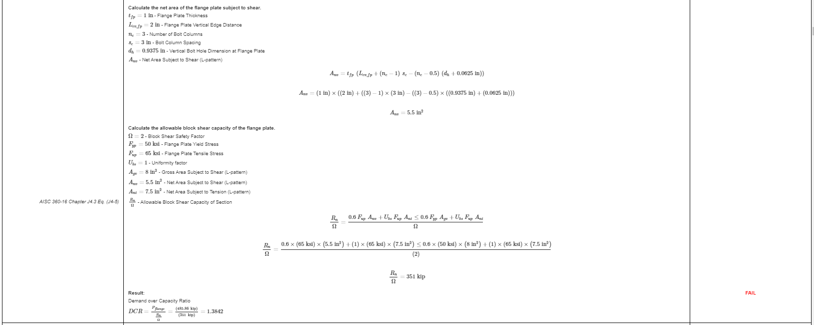
What you see above is a snippet of the detailed calculation report. As you can see, there is a reference to the AISC manual and/or specification. This should make it easier for the signing engineer to cross-check the calculations. Our calculations are very readable. It is written similar to how it’s written in the manual, specification, or design guides.
Here‘s a PDF copy of the full detailed calculation report. Check it out!