Export Simplified Structural Drawings for Reinforced Concrete and Steel Structures
Getting Started
SkyCiv’s Drawings feature allows you to export your S3D model to a DXF file, creating structural plans and horizontal views according to an automated algorithm or using the gridlines and elevations. For concrete members, you can also export the reinforcement information and add seismic provisions for detailing assigned using the SkyCiv RC Design Module. If this data has been entered, you will see it appear in the Drawings Settings (shown in a below step).
To export your drawing, click on Output – Drawings which will display the below Settings Modal. If your model has concrete members, you can add the additional information required in the UI and click “Export DXF”.
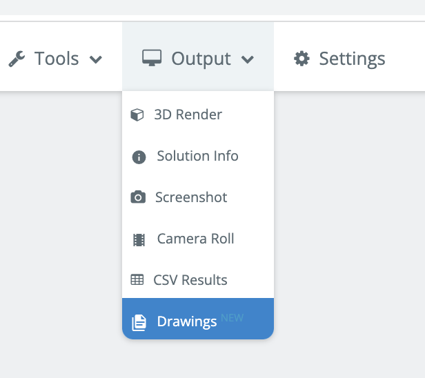
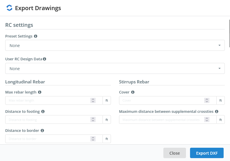
Image 1 Drawings Feature in S3D
Understanding your Drawings
Elevation View
The elevation view shows a vertical projection for each elevation defined in the model or automatically selected, including any gridlines and elevations entered under Gridlines & Elevations:
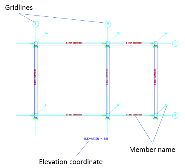
Image 2 Elevation view
Horizontal View
The horizontal view shows a projection according to the planes created by the gridlines or automatically created.
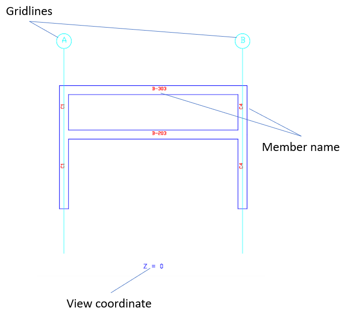
Image 3 Horizontal view
Inclined Views
This feature includes an additional view for inclined members, automatically creates all 2D planes necessary, and shows a projection of the plane. This is particularly useful on inclined structures, for instance solar frames:
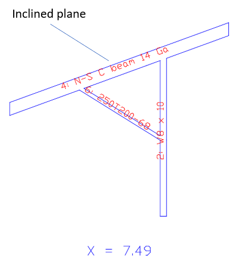
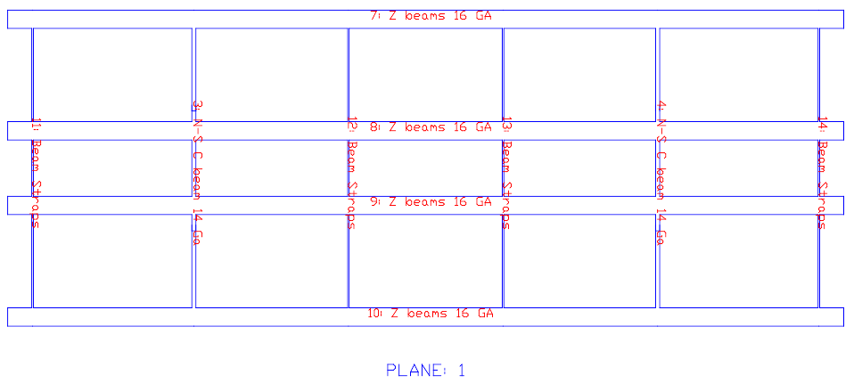
Image 4 Inclined view
Member Text Guide
Each member has a text associated with the following information, specific to each member and section:
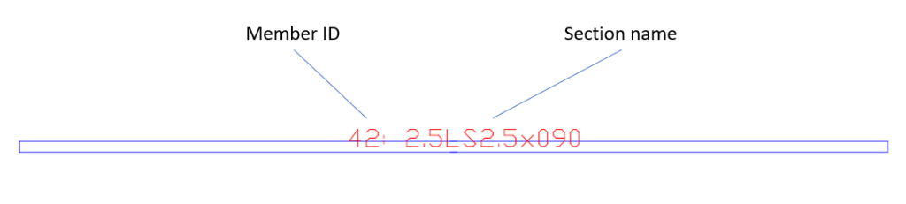
Image 5 Member text
Drawing Units
The drawings are created in meters (m) for the Metric unit system or in feet (ft) for the Imperial unit system. The input of your model is independent of the drawings. For instance, if you have a model with length units as mm, it will still display the drawings in m.
Concrete Members
For concrete members you can create details for each beam and column, depending on your country requirements. The Settings Modal below shows some of the input required for accurate concrete drawings. SkyCiv has also set some preset country codes to automate this input for you:
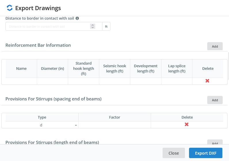
Image 6 UI concrete Settings
UI Settings
- Preset settings: this allows you to select some predefined settings for RC detailing according to some design codes.
- User RC design data: this allows you to select the RC data stored in the server, this is the data used to create reinforcement detailing.
- Max rebar length: Set the maximum longitudinal rebar length in detailing, the rebar will be overlapped using the Lap splice length so the drawings will not generate bars longer than this length.
- Distance to footing: for columns, this is the distance from the bottom of the member to the footing, used to calculate the length of the longitudinal bars.
- Distance to border: This is the distance of a longitudinal bar to the border of the element.
- Distance to border in contact with soil: This is the distance of a longitudinal bar of a column to the border of the element at the bottom side.
- Cover: cover for stirrups, used to calculate the length of the stirrup.
- Maximum distance between supplemental crossties: if the distance between ties in columns is bigger than this value will add the necessary ties to the transversal detail.
- Reinforcement bar information: you can set the information for the reinforcement bars used in the drawing.
- Provisions for stirrups: here you can add some settings to limit the maximum spacing of stirrups according to some of the parameters used in the design codes, you can add many checks you need. The check value is the multiplication of “Type” with the “Factor”, if you select the length Type will use the Factor value as a length.
Standard provisions for detailing
Many standards include additional provisions outside of the main specification that affect the detailing of structures, some of them are related to the seismic provisions. Adequate detailing allows the members part of the seismic-force-resisting-system a good behaviour during seismic events with a proper energy dissipation capacity, avoiding plastic hinges in the columns and limiting them to special zones of the beams. When there are RC settings available this feature checks the design data available and adjusts it if necessary.
Beam details
A beam detail is created with different continuous segments that share the same section and have a relative angle between consecutive segments of less than 15°. The lap splices are located in the center of the span for the top bars and near the supports for the bottom bars.
Each beam detail includes the longitudinal and transversal reinforcement, gridlines, and section detail.
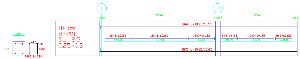
Image 7 Beam detail
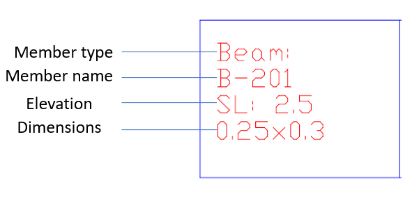
Image 8 Beam information
Column Details
Column details also include the longitudinal and transversal reinforcement, section detail, and levels. Are created with continuous vertical segments.
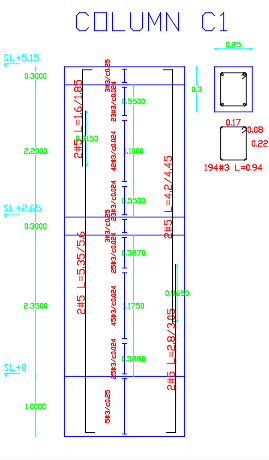
Image 9 Column detail
Reinforcement Bars
The reinforcement bars are drawn in the layer “REINFORCEMENT_LAYER” with the necessary hooks. The reinforcement bar object has associated a text with the number of bars, bar name, the straight length, and total length.
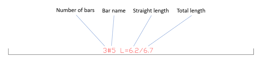
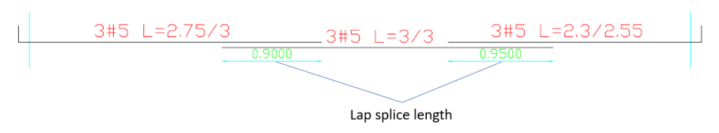
Image 10 Reinforcement bars
Stirrups
The stirrup object is a group of stirrups with the same spacing.
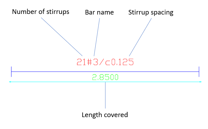
Image 11 Stirrups
Section Details
Every member has a section detail that shows the section shape, dimensions, and stirrups.
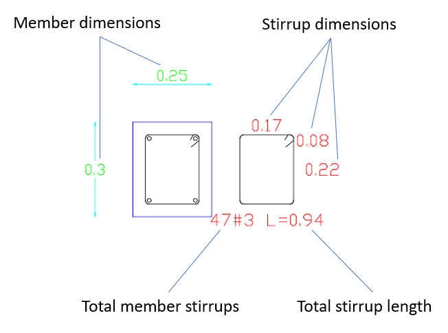
Image 12 Section detail
Multiple Layer Reinforcement
When there are multiple layers defined in the design module the Drawings feature recognize different layer the ones with a different position. Automatically the outermost layers from top and bottom are defined as continuous layers with bars overlapped according to the lap splice lengths, other layers are created as non-continuous layers with the bars extended by the development lengths.
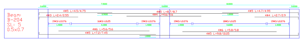
Image 13 Multiple layer reinforcement