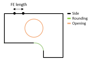
To generate beam FE mesh you need to define element size on all the edges of a beam (On side length), like web, flanges, and stiffeners. Also, you can manage the element size on the edge of openings (On opening length) and zones of web transition through the radius (On rounding length). If to click the Preview button, you will see how the mesh nodes will be distributed on all the edges before mesh generation. Click Generate button to create the mesh.
Example of meshing

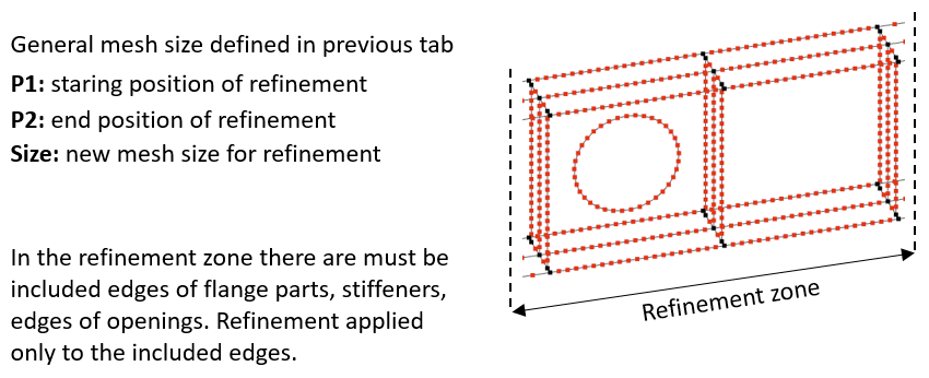
The mesh size can also be controlled locally. This is suitable when you need to focus your attention in stress distribution or deformation in specific zones of a beam, where the dense mesh must be included. Such zones can be web panels between vertical stiffeners. The web parts’ edges, flange parts’ edges, opening edges or stiffeners edges that are included in the defined zone length can be remeshed by the new local mesh size. Follow the example below.
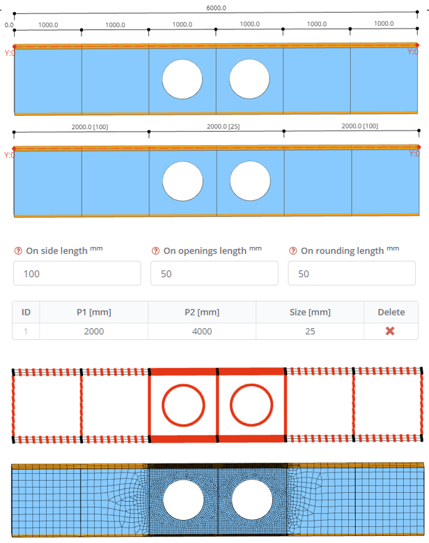
Example of meshing refinement
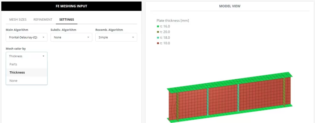
In the Settings the mesh structure type can be managed by user. Generated mesh can be colored by fixed colors for beam parts and by different colors based on the plate thicknesses.
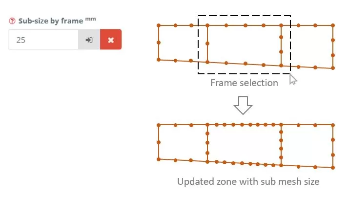
In the Member Shell FEA software additionally can be used sub-meshing. First, enter the desired sub-mesh FE size in the input field. Next, click the button to select the model edges for adjusting the model’s FE size. If you wish to revert to the original FE size, click ‘X’.