The Operations group in the right toolbar contains geometry editing tools for trimming, extending, splitting, joining, scaling, and property matching.
Most operations work on selected geometry. Use the active snap settings for precise picks and target points.
Operations
Operations tools are grouped into drop-down stacks in the right bar. Click the category button to activate the current tool, or open the mini toolbar to choose another tool in the same stack.
Match Properties
Copy style and attribute properties from one object to others
The Match Properties command applies properties from a source object to compatible target objects.
Step-by-step
- 1Select a source object to copy its properties from.
- 2Click Match Properties to activate brush mode.
- 3Click compatible target elements to apply properties instantly.
- 4Continue clicking, or use fence or window selection for multiple targets.
- 5Press Esc to exit brush mode.
Tip: Match Properties copies visual properties such as color, line weight, line style, and layer. Only properties compatible with the target object type are applied.
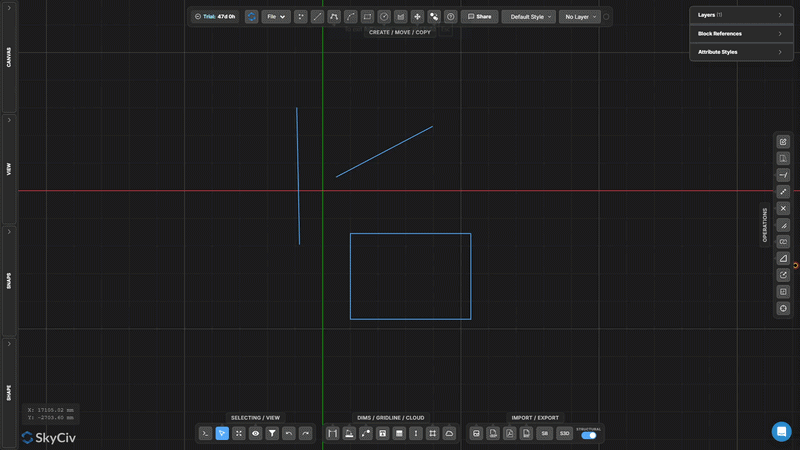
Stretch
Move selected vertices using a crossing window or lasso
Stretch moves vertices while preserving topology around connected geometry.
[__INSERT_IMAGE__]
Step-by-step
- 1Activate Stretch.
- 2Select vertices with a right-to-left crossing window or lasso.
- 3Drag the center handle for a free move, or the X/Y handles for a constrained move.
Tip: Only the vertices inside the crossing selection are moved; lines connected to those vertices outside the selection are stretched to maintain connectivity.
Extend Line
Extend a line until it meets a target line or point
Extend Line lengthens a selected line to meet a target boundary. The line is extended along its existing direction until it intersects the picked target.
Step-by-step
- 1Activate Extend Line.
- 2Click the line to extend (near the end you want to grow).
- 3Click the target line or point to extend to.
Tip: Click near the end of the line you want extended – the tool extends from the nearest endpoint in the direction of the target.
Trim
Remove line or arc segments defined by cutting edges
Trim removes portions of lines or arcs using other geometry as cutting edges. First select the cutting edges, confirm them, then click or fence the segments you want to remove.
Step-by-step
- 1Activate Trim.
- 2Select the cutting edge geometry (lines, arcs, circles).
- 3Press Enter or Spacebar to confirm cutting edges.
- 4Click or fence the segments to remove.
Tip: You can use a window or fence selection to trim multiple segments simultaneously after confirming the cutting edges.
Split Line into Segments
Divide a line into N equal segments
Split Line into Segments divides a single line into a specified number of equal-length segments. Each resulting segment is an independent line element.
Step-by-step
- 1Activate the tool.
- 2Click the line to split.
- 3Enter the number of divisions and press Enter.
Tip: Useful for creating equally spaced support points along a beam or dividing a span for load distribution analysis.
Split Line by Interval
Split a line into repeated fixed-length intervals
Split Line by Interval divides a line into segments of a specified fixed length. A remainder segment is created at the end if the line length is not a whole multiple of the interval.
Step-by-step
- 1Activate the tool.
- 2Click the line to split.
- 3Enter the interval length and press Enter.
Tip: Use this for creating evenly spaced intermediate nodes along a continuous member at a known spacing (e.g., every 500 mm for joist layout).
Split by Position along Line
Split a line at an offset distance from one of its endpoints
Split by Position inserts a break point at a measured distance from one end of the selected line, creating two separate segments at that offset position.
Step-by-step
- 1Activate the tool.
- 2Click a line (the click position determines which endpoint to measure from).
- 3Enter the offset distance and press Enter.
Tip: Click near the endpoint you want to measure from – the tool uses the nearest endpoint as the reference for the offset distance.
Split Lines at Intersections
Automatically split all selected lines at crossing points
Split Lines at Intersections finds all points where selected lines cross each other and inserts split nodes at each intersection. No input values are required – the operation is fully automatic.
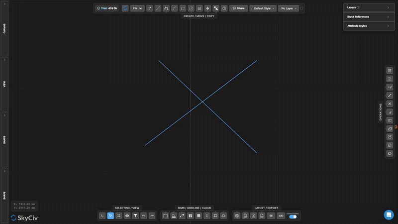
Step-by-step
- 1Select the lines to process.
- 2Click Split Lines at Intersections.
- 3All crossing intersections are detected and split automatically.
Tip: Run this before using Joint Selection or performing topology-dependent operations – it ensures crossing lines share actual node points.
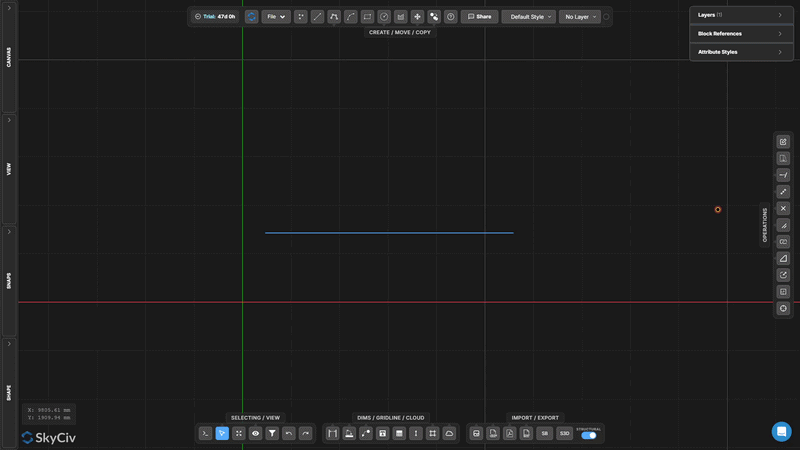
Split Target
Split pre-selected target objects using separate splitter geometry
Split Target is a two-stage split where you first mark the objects to be split (targets), then separately select the geometry to split them with (splitters). Only target objects are cut.
[__INSERT_IMAGE__]
Step-by-step
- 1Pre-select the target objects to be split.
- 2Activate Split Target.
- 3Select the splitter geometry.
- 4Press Enter to split targets at intersections with splitters.
Tip: Use Split Target when you want to split specific lines with a cutting edge but need to preserve the cutting geometry intact (unlike Trim, which also modifies the cutter).
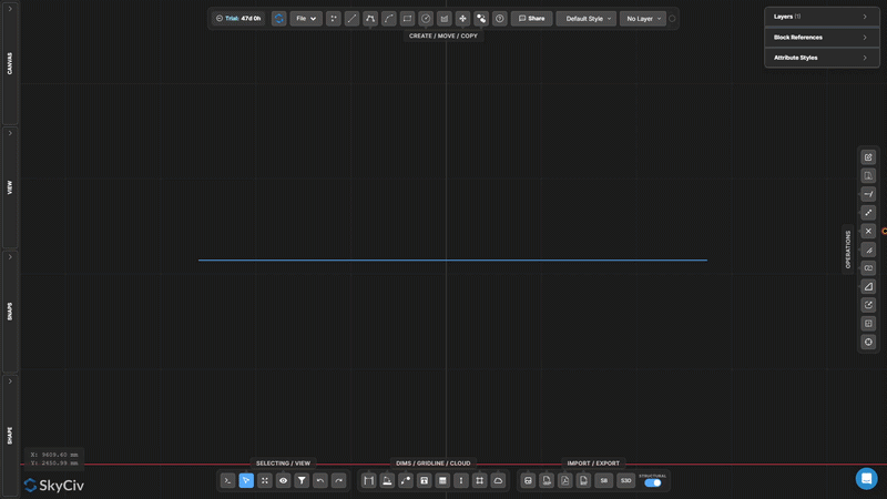
Split at Overlaps
Detect and separate overlapping collinear line segments
Split at Overlaps finds segments of selected lines that are collinear and overlap each other, then splits them so the overlapping regions become discrete, individually selectable geometry.
[__INSERT_IMAGE__]
Step-by-step
- 1Select lines that may have overlapping collinear portions.
- 2Click Split at Overlaps.
- 3Overlapping regions are split into separate segments.
Tip: Combine with Select Duplicates to identify and remove redundant overlapping lines in imported DXF files.
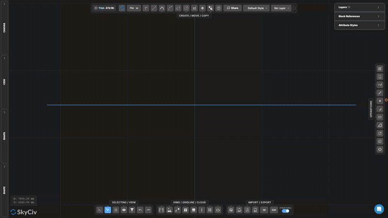
Explode Polyline
Break a polyline into independent line or arc segments
Explode Polyline decomposes a multi-segment polyline into individual independent segments. Useful when you need to edit, delete, or apply operations to only part of a polyline.
[__INSERT_IMAGE__]
Step-by-step
- 1Select the polyline to explode.
- 2Click Explode Polyline.
- 3Each segment becomes individually selectable and editable.
Tip: The inverse operation is Join Lines and Arcs, which merges connected segments back into a single polyline.
Join Lines and Arcs
Merge connected lines and arcs into a single polyline
Join Lines and Arcs combines a chain of connected segments into a single continuous polyline object. Lines and arcs must share endpoints to be joined.
Step-by-step
- 1Select lines and arcs that share endpoints.
- 2Click Join Lines and Arcs.
- 3Connected segments merge into one continuous polyline.
Tip: All selected segments must form a single continuous chain. If segments have gaps, use Snap to Line Ends and the Move Point tool first to close the endpoints.
Create Fillet
Round a sharp corner between two lines with an arc
Create Fillet replaces a sharp corner between two lines with a tangent arc of a specified radius. The original line ends are trimmed to accommodate the arc.
Step-by-step
- 1Activate Create Fillet.
- 2Set the fillet radius in the dialog.
- 3Click the corner (intersection area) of the two lines to apply.
Tip: The radius must be small enough to fit within the lengths of both lines from the corner. A live preview is shown before confirming.
Create Chamfer
Create a straight bevel cut at a corner
Create Chamfer cuts a straight diagonal bevel across a corner between two lines. Set the chamfer distance to control how far back from the corner each line is trimmed.
Step-by-step
- 1Activate Create Chamfer.
- 2Set the chamfer distance in the dialog.
- 3Click the corner geometry to apply the chamfer.
Tip: Chamfer cuts equally from both lines by default. For an asymmetric bevel (different distances on each side), set two separate chamfer values in the dialog.
Scale Objects
Scale selected geometry by a factor from a pivot point
Scale Objects resizes selected geometry by a uniform scale factor relative to a chosen pivot point. A dialog lets you choose whether annotations (dimensions, text, leaders, gridlines, tables) are also scaled.
Step-by-step
- 1Select the objects to scale.
- 2Click Scale Objects and configure annotation scale options in the dialog.
- 3Click the canvas to set the scale pivot (origin) point.
- 4Type the scale factor and press Enter (1.0 = no change, 0.5 = half, 2.0 = double).
Tip: Use the Scale Options dialog to control whether annotation sizes (dimensions, text, leaders, tables) scale with the geometry or remain at their current sizes.
Scale Frame
Create a persistent local scale zone with a visible frame
Scale Frame creates a persistent rectangular zone with an associated scale factor. Geometry drawn or placed inside the frame is rendered at that local scale. Useful for detail callouts at a different drawing scale.
[__INSERT_IMAGE__]
Step-by-step
- 1Activate Scale Frame.
- 2Click the first corner, then the opposite corner to define the frame.
- 3Type the scale factor in the input and press Esc to apply.
Tip: The frame persists on canvas after creation. Select and delete it when no longer needed. The scale input remains available for later editing while the frame is selected.
Update Origin
Move the drawing coordinate origin (0,0) to a new location
Update Origin relocates the drawing’s reference coordinate system. All coordinate values (X, Y) displayed in the canvas and exported in data are recalculated relative to the new origin.
[__INSERT_IMAGE__]
Step-by-step
- 1Activate Update Origin.
- 2Click the new origin location on the canvas.
- 3Coordinate readouts update immediately relative to the new (0,0) point.
Tip: Snap to an existing node for a precise new origin. For structural drawings, snap to a known column or datum intersection to align coordinates with the project reference grid.
Unlock your
Free Account
Register for a free account and get access to powerful analysis + design software:
✓ Powerful Analysis Software
✓ Access to 90+ Design Tools
✓ ASCE, AS, EN, NBCC Load Generator
✓ Steel, Timber, Concrete, Aluminum