Calculation guide in designing an isolated footing based on CSA A23.3-14
SkyCiv Foundation covers the design of isolated footing conforming to CSA A23.3-14¹ and NBCC 20102.
Want to try SkyCiv’s Foundation Design software? Our tool allows users to perform Foundation Design calculations without any download or installation!
Design Parameters of an Isolated Footing
Some calculations presented are similar with ACI 318, which is also one of the references of its CSA counterpart.
Dimension Requirements
To determine the dimensions of an isolated footing, service or unfactored loads, such as dead (D), Live (L), Wind (W), Seismic (E), etc will be applied using Load Combinations, as defined by NBCC 2010. Whichever Load Combination governs will be considered the design load, and will be divided to the allowable soil pressure as shown in Equation 1.
\(\text{A} = \frac{\text{P}_{\text{n}}}{\text{q}_{\text{all}}} \rightarrow \) Equation 1
where:
qall = allowable soil pressure
Pn = unfactored design load
A = Foundation area
One-way Shear
To check for one-way shear, the Critical Shear Plane (Refer to Figure 1) is located at a distance “d” from the face of a column.
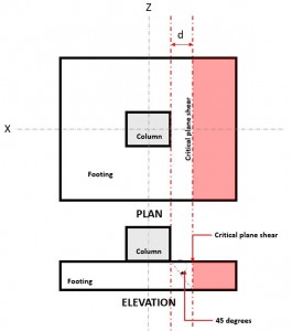
Figure 1. Critical Plane Shear of One-way shear
The One-way Shear Demand or Vf is calculated assuming the footing is cantilevered away from the column where the area is (red) indicated in Figure 2, in accordance of CSA A23.3-14, Section 13.3.6.
The One-way Shear Capacity or Vc is defined as Ultimate shear strength and calculated using Equation 2 per CSA A23.3-14, Section 11.3.4.
\(\text{V}_{\text{c}} = \phi _{\text{c}} \times \lambda \times \sqrt{\text{f’}_{\text{c}}} \times \text{b}_{\text{w}} \times \text{d} \rightarrow \) Equation 2 (CSA A23.3-14 Eq. 11-6)
where:
ϕc = resistance factor for concrete
λ = modification factor for concrete density
f’c = specified concrete strength, MPa
bw = width of the footing, mm
d = effective shear depth, mm
Shear Demand and Shear Capacity must meet the following equation to meet the design requirements of CSA A23.3-14:
\(\text{V}_{\text{f}} \leq \phi\text{V}_{\text{c}} \rightarrow \) Equation 3 (CSA A23.3-14 Eq. 11.3)
SkyCiv Foundation, in compliance of Equation 3, calculates the one-way shear unity ratio (Equation 4) by taking Shear Demand over Shear Capacity.
\( \text{Unity Ratio} = \frac{\text{Shear Demand}}{\text{Shear Capacity}} \rightarrow \) Equation 4
Two-way Shear
The Two-way Shear limit state, also known as punching shear, extends it critical section to a distance “d/2” from the face of the column and around the perimeter of the column. The Critical Shear Plane is located at that section of the footing (Refer to Figure 2).
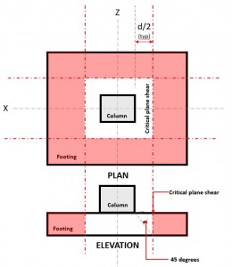
Figure 2. Critical Shear Plane of Two-way shear
The Two-way Shear Demand or Vf occurs at the Critical Shear Plane, located a distance of “d/2” where the (red) hatched area, indicated in Figure 2, in accordance of CSA A23.3-14, Section 13.3.3.
The Shear Capacity or Vc is governed by the least value calculated using Equation 5, 6, and 7 per CSA A23.3-14, Section 13.3.4.1
\(\text{V}_{\text{c}} = \left ( 1 + \frac{2}{\beta_{\text{c}}} \right ) \times 0.19 \times \lambda \times \phi _{\text{c}} \times \sqrt{f’_{c}} \rightarrow \) Equation 5 (CSA A23.3-14 Eq. 13.5)
\(\text{V}_{\text{c}} = \left ( \frac{\alpha_{\text{s}} \times \text{d}}{\text{b}_{\text{o}}} + 0.19 \right ) \times \lambda \times \phi _{\text{c}} \times \sqrt{f’_{c}} \rightarrow \) Equation 6 (CSA A23.3-14 Eq. 13.6)
\(\text{V}_{\text{c}} = 0.38 \times \lambda \times \phi _{\text{c}} \times \sqrt{f’_{c}} \rightarrow \) Equation 7 (CSA A23.3-14 Eq. 13.7)
Note: βc is the ratio of long side to short side of the column, concentrated load, or reaction area and αs is given by 13.3.4.1
where:
λ = modification factor for concrete density
f’c = specified compressive concrete strength, MPa
d = distance from extreme compression fiber to centroid of longitudinal tension reinforcement, mm
Shear Demand and Shear Capacity must meet the following equation to meet the design requirements of CSA A23.3-14:
\(\text{V}_{\text{f}} \leq \phi\text{V}_{\text{c}} \rightarrow \) Equation 8 (CSA A23.3-14 Eq. 11.3)
SkyCiv Foundation, in compliance of Equation 8, calculates the two-way shear unity ratio (Equation 9) by taking Shear Demand over Shear Capacity.
\( \text{Unity Ratio} = \frac{\text{Shear Demand}}{\text{Shear Capacity}} \rightarrow \) Equation 9
Flexure
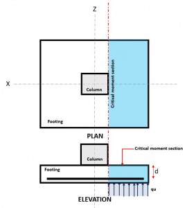
Figure 3. Critical Flexure Section
The Flexural limit state occurs at the Critical Flexure Section, located at the face of the column on top of the footing (Refer to Figure 3).
The Moment Demand, or Mf is located at the Critical Flexure Section (blue hatch area) indicated in Figure 3, and is calculated using Equation 10.
\( \text{M}_{u} = \text{q}_{u} \times \left ( \frac{l_{x}}{2} – \frac{c_{x}}{2} \right ) \times l_{z} \times \left ( \frac{\frac{l_{x}}{2} – \frac{c_{x}}{2} }{2} \right ) \rightarrow \) Equation 10
where:
qu = factored soil pressure, kPa
lx = footing dimension along the x-axis, mm
lz = footing dimension along the z-axis, mm
cx = column dimension along the x-axis, mm
The Moment Resistance, or Mr is calculated using Equation 11.
\( \text{M}_{r} = \phi_{\text{s}} \times A_{s} \times f_{y} \times \left( d – \frac{a}{2} \right) \rightarrow \) Equation 11
where:
ϕs = resistance factor for non-prestressed reinforcing bars
d = distance from extreme compression fiber to centroid of longitudinal tension reinforcement, mm
As = reinforcement area, mm2
a = depth of equivalent rectangular stress block, mm
fy = reinforcement strength, MPa
Moment Demand and Moment Resistance must meet the following equation to meet the design requirements of CSA A23.3-14:
\(\text{M}_{\text{r}} \leq \phi\text{M}_{\text{f}} \rightarrow \) Equation 12
SkyCiv Foundation, in compliance of Equation 12, calculates the flexural unity ratio (Equation 13) by taking Flexural Demand over Flexural Capacity.
\( \text{Unity Ratio} = \frac{\text{Flexure Demand}}{\text{Flexure Capacity}} \rightarrow \) Equation 13
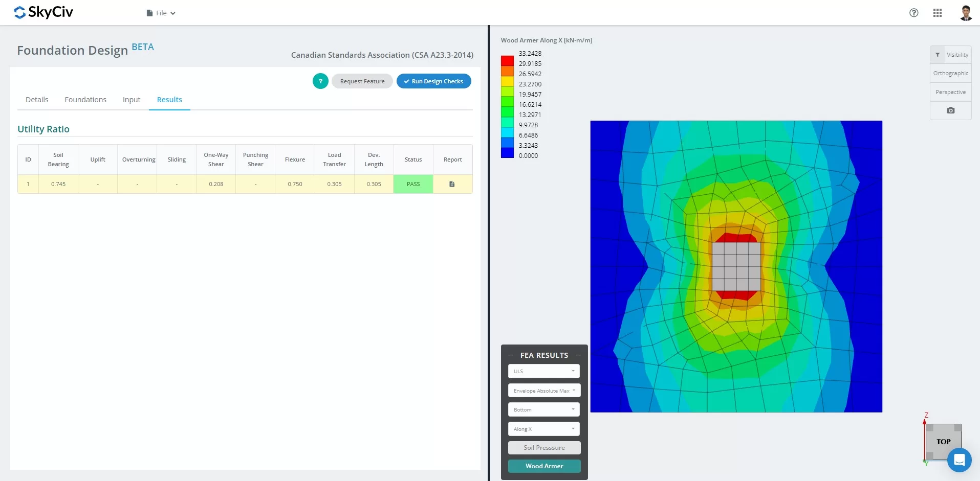
NEW SkyCiv Foundation with FEA
As of March 2024, the Foundation Design Module has integrated the Finite Element Analysis (FEA) solver into its capabilities. This new feature allows users to conduct in-depth soil pressure and wood armer analyses while still performing all structural checks specified by CSA A23.3-14, including all verifications mentioned above. Summary of the FEA Results is included in the comprehensive report.
Free Concrete Footing Calculator
Try SkyCiv Free Concrete Footing Calculator to design foundations for footings, combined footings, concrete piles, concrete pads, and more.
References
- A23.3-14: Design of concrete structures. Canadian Standards Association, 2014.
- Brzev and Pao. Reinforced Concrete Design: A Practical Approach, 2009.

Product Developer
BSc, MEng (Civil)