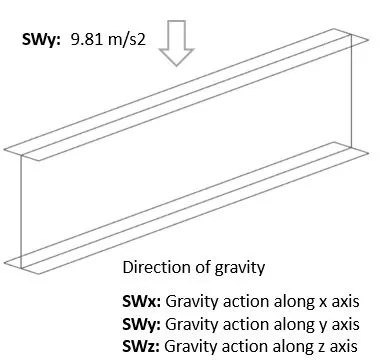
Self weight
Gravity force at specified direction. Weight of elements is taken from the model geometry and material density.
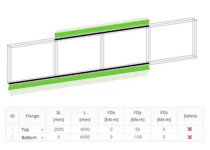
Distributed
The distributed loads are applied to the nodes of the top and bottom edges of a beam web. Here you select the flange on which the load is applied, from where the distribution is started (SL), the length of distribution (L), and the directed load value per unit length (FD). The nodal loads with the values can be previewed by clicking on the Preview button.
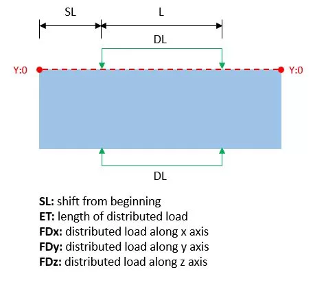
Example of input
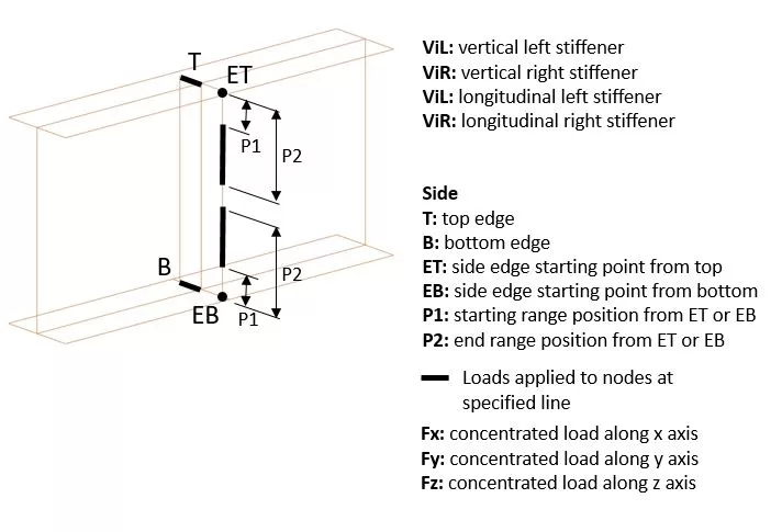
Stiffeners
The concentrated loads can be applied to the nodes arranged on the edges of stiffeners. Here in the table row, you select the stiffener and its edge and then define the directed load with its value. The load will be distributed among the nodes of the selected edge. The nodal loads with the values can be previewed by clicking on the Preview button.
Examples of input
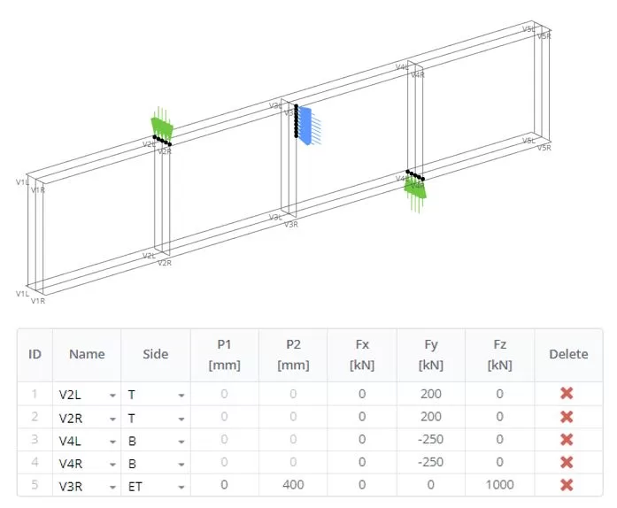
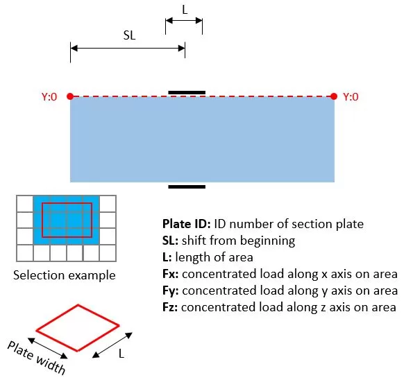
Plate Area
The load is applied to the area on a plate. Here you select the plate ID, position of the center of a load area from the left side of a beam (SL), length (L), and width (B) of the area, and directed force with its value. The load will be distributed among the nodes inside the area. The nodal loads with the values can be previewed by clicking on the Preview button.
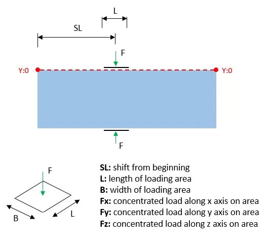
Area
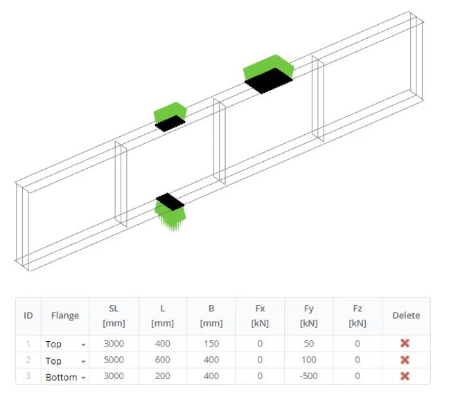
The load is applied to the area on a beam flange. Here you select the flange, position of the center of a load area from the left side of a beam (SL), length (L), and width (B) of the area, and directed force with its value. The load will be distributed among the nodes inside the area. The nodal loads with the values can be previewed by clicking on the Preview button.
Examples of input
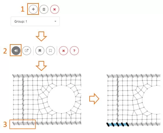
Force Area (Custom)
The specified load can be distributed amog the selected group of finite elements. Start by creating a new group using the ‘+’ button. Then, select the elements and define forces for them. If you need different forces, create another group for elements. Selection or deselection can be achieved using either the frame or polygon tools
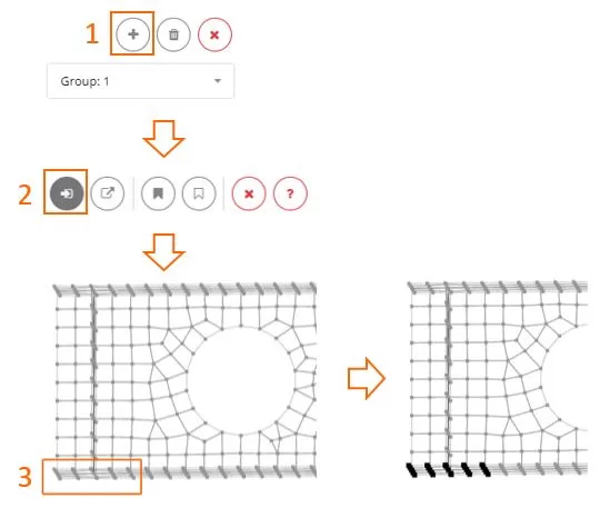
Force Nodal (Custom)
The specified directional force can be applied to each node within the selected group. Start by creating a new group using the ‘+’ button. Then, select the nodes and define forces for them. If you need different forces, create another group for nodes. Selection or deselection can be achieved using either the frame or polygon tools
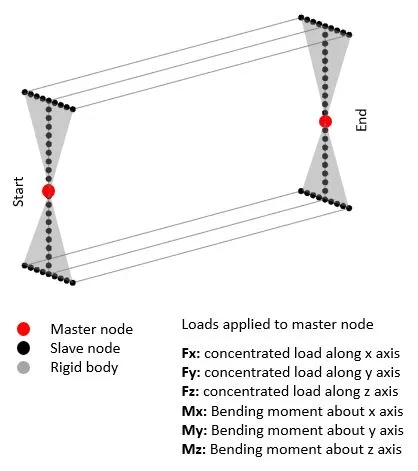
Beam Ends
Here you can apply the load to the beam’s left or right side. The side section will be considered as the rigid body system with the master node at the section centroid and all the side edge nodes will be slave nodes. The directed load is applied to the master node. If you click on the Preview button, you may see the load applied to the master node with the value.
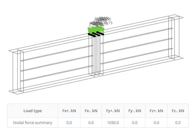
Preview All
The loads can be defined by different methods and for visual inspection of the finial nodal forces you can check it in the table and 3D view.
Load Amplitude
The applied load is incorporated into the load-time amplitude group. For more details, refer to Analysis > Load Amplitude