Slabs systems considered by the standard
Australian Standards establish the minimum requirements for the design of reinforced concrete slabs, such as one-way and two-way types. Regarding the plan configuration and the inclusion of beams, the slabs can also be divided into slabs supported on four sides, beam-and-slab systems, flat slabs, and flat plates. These types are summarized in the following images.
Simplify Australian slab design compliance with SkyCiv’s advanced Concrete Structure Design Software. Try it out! Easily apply AS 3600 checks for slabs and flat plates.
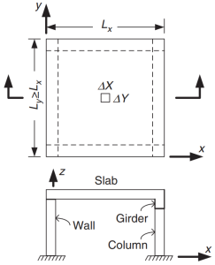
Figure 1. Slab supported on four sides. (Yew-Chaye Loo & Sanual Hug Chowdhury , “Reinforced and Prestressed Concrete”, 2nd edition, Cambridge University Press).
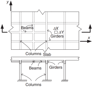
Figure 2. Grillage Slab System. (Yew-Chaye Loo & Sanual Hug Chowdhury , “Reinforced and Prestressed Concrete”, 2nd edition, Cambridge University Press).
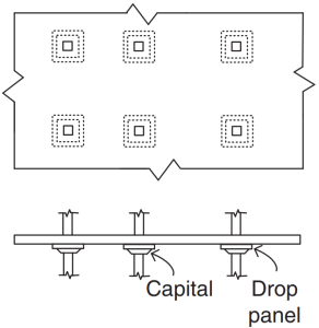
Figure 3. Flat Slabs. (Yew-Chaye Loo & Sanual Hug Chowdhury , “Reinforced and Prestressed Concrete”, 2nd edition, Cambridge University Press).
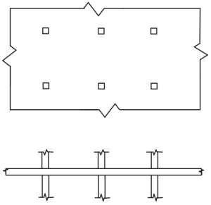
Figure 4. Flat Plates. (Yew-Chaye Loo & Sanual Hug Chowdhury , “Reinforced and Prestressed Concrete”, 2nd edition, Cambridge University Press).
The Standard recommends some methods (simplified and proven procedures) in determining bending moments:
- Clause 6.10.2: Continous beams and one-way slabs
- Clause 6.10.3: Two-way slabs supported on four sides
- Clause 6.10.4: Two-way slabs having multiple spans
The purpose of the code is to design the total amount of reinforcement steel rebar into principal directions in the slab system. Rebar steel will be calculated for the bending moments “Mx” and “My.” Figure 5 shows the other forces or actions in a finite slab element in which the code prescribes their resistance values.
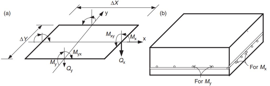
Figure 5. Forces in a finite slab element: bending moments (Mx, My), twisting moments (Mxy, Myx), and shears (Qx, Qy). (Yew-Chaye Loo & Sanual Hug Chowdhury , “Reinforced and Prestressed Concrete”, 2nd edition, Cambridge University Press)
In this article, we will develop two slab design examples, one-way and two-way slab systems, using the simplified methods oriented and permitted by the code. In both instances, we will create a SkyCiv S3D model and compare the results against the methods mentioned above.
If you are new at SkyCiv, Sign up and test the software yourself!
One-Way Slab Design Example
Shown below is the small building and the slabs we will design
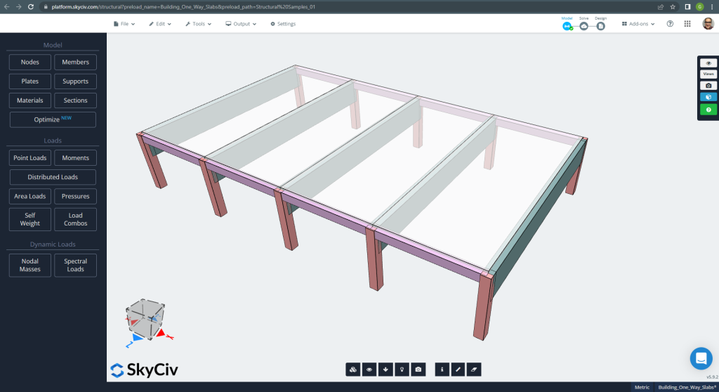
Figure 6. One-way slabs in a small building example. (Structural 3D, SkyCiv Cloud Engineering).
The plan dimensions are shown at next
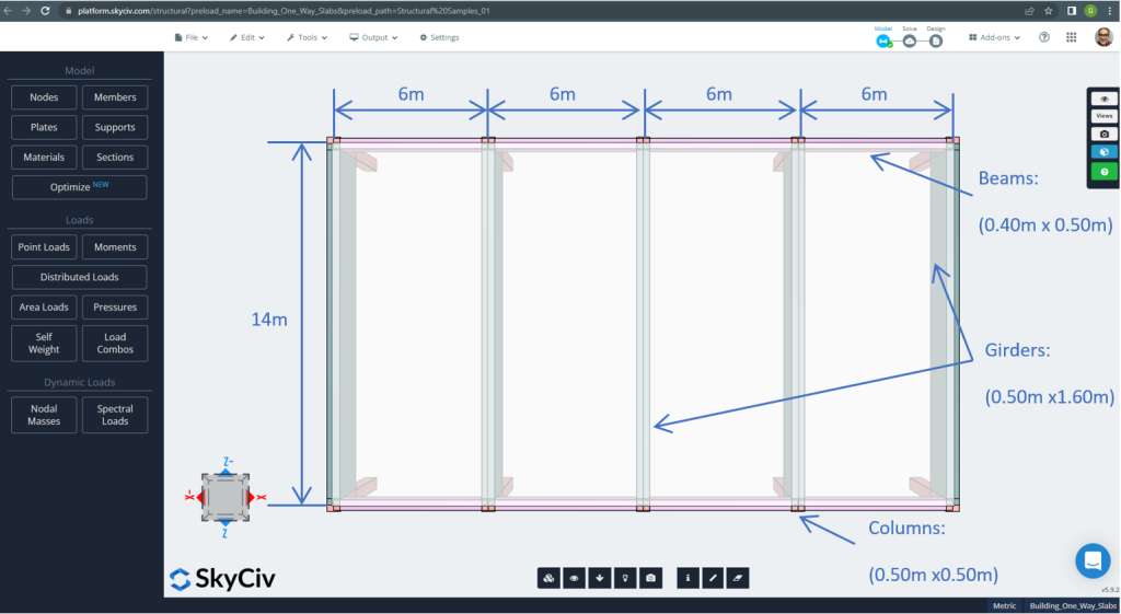
Figure 7. Plan dimensions and structural elements. (Structural 3D, SkyCiv Cloud Engineering).
For the slab example, in summary, the material, elements properties, and loads to consider :
- Slab type classification: One – way behaviour \(\frac{L_2}{L_1} > 2 ; \frac{14m}{6m}=2.33 > 2.00 \) Ok!
- Building occupation: Residential use
- Slab thickness \(t_{slab}=0.25m\)
- Reinforced concrete density assuming a steel reinforcement ratio of 0.5% \(\rho_w = 24 \frac{kN}{m^3} + 0.6 \frac{kN}{m^3} \times 0.5 = 24.3 \frac{kN}{m^3} \)
- Concrete characteristic compressive strength at 28 days \(f’c = 25 MPa \)
- Concrete Modulus of Elasticity by Australian Standard \(E_c = 26700 MPa \)
- Slab Self-Weight \(Dead = \rho_w \times t_{slab} = 24.3 \frac{kN}{m^3} \times 0.25m = 6.075 \frac {kN}{m^2}\)
- Super-imposed dead load \(SD = 3.0 \frac {kN}{m^2}\)
- Live load \(L = 2.0 \frac {kN}{m^2}\)
Hand calculation according to AS3600 Standard
In this section, we will calculate the required reinforced steel rebar using the reference of the Australian Standard. We first obtain the total factored bending moment to be carried out by the slab’s unitary width strip.
- Dead load, \(g = (3.0 + 6.075) \frac{kN}{m^2} \times 1 m = 9.075 \frac{kN}{m}\)
- Live load, \(q = (2.0) \frac{kN}{m^2} \times 1 m = 2.0 \frac{kN}{m}\)
- Ultimate load, \(Fd = 1.2\times g + 1.5\times q = (1.2\times 9.075 + 1.5\times 2.0)\frac{kN}{m} =13.89 \frac{kN}{m} \)
Using the simplified method specified by the standard, first, it is a must to comply with the following restrictions:
- \(\frac{L_i}{L_j} \le 1.2 . \frac{6m}{6m} =1 < 1.2 \). Ok!
- Load has to be uniform. Ok!
- \(q \le 2g. q=2 \frac{kN}{m} < 18.15 \frac{kN}{m}\). Ok!
- The slab cross-section has to be uniform. Ok!.
Recommended minimum thickness, d
\(d \ge \frac{L_{fe}}{{k_3}{k_4}{\sqrt[3]{\frac{\frac{\Delta}{L_{ef}}{E_c}}{F_{d, ef}}}}}\)
Where
- \(k_3 = 1.0; k_4 = 1.75 \)
- \(\frac{\Delta}{L_{ef}}=1/250 \)
- \(E_c = 27600 MPa \)
- \(F_{d,ef} = (1.0 +k_{cs})\times g + (\psi_s + k_{cs}\times \psi_1) \times q=(1.0+0.8)\times 9.075 + (0.7+0.8\times 0.4)\times 2 = 18.375 kPa\)
- \(\psi_s = 0.7 \) Live-load short-term factor
- \(\psi_1 = 0.4 \) Live-load long-term factor
- \(k_{cs} = 0.8 \)
\(d \ge \frac{5.50m}{{1.0}\times {1.75}{\sqrt[3]{\frac{\frac{1}{250}\times{27600 \times 10^3 kPa}}{18.375 kPa}}}} \ge 0.173m. d = 0.25m > 0.173m \) Ok!
Once we demonstrate that constraints are satisfied, the bending moment is calculated using the expression: \(M=\alpha \times F_d \times L_n^2\) where \(\alpha\) is a constant defined in the following figure.
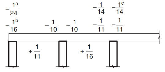
Figure 8. Values of moment coefficient \(\alpha\) for slabs with more than two spans. (Yew-Chaye Loo & Sanual Hug Chowdhury , “Reinforced and Prestressed Concrete”, 2nd edition, Cambridge University Press).
Where:
- (a) Case of slabs and beams on girder support
- (b) For continuous beam support only
- (c) Where Class L reinforcement is used
- \(L_n \) is the unitary strip span
- \(F_d \) is the gravitational factored load
For the slab example, we have to use case (a) because the slab rests on stiff girders. It will be explained only one case and the rest will show in the following table. We include also the steel reinforcement area calculation.
- \(M={\alpha} {F_d}{L_n^2}={-\frac{1}{24}}\times {13.89 \frac{kN}{m}}\times (6m-0.5m)^2 = – 17.51{kN}{m}\)
- Cover = 20mm (A minimum of 10mm is needed for fire resistance period of 60 minutes).
- \(d = t_{slab} – Cover – \frac{BarDiameter}{2} = 250mm – 20mm – 6mm = 224mm \)
- \(\alpha_2 = 1.0-0.003 f’c = 1.0-0.003\times 25 = 0.925 (0.67 \le \alpha_2 \le 0.85) \) Thus, we select \(\alpha_2 = 0.85\)
- \(\xi = \frac{\alpha_2\times f’c}{f_{sy}} = \frac{0.85\times 25 MPa}{500 MPa} = 0.0425 \)
- \(\rho_t = \xi – \sqrt{{\xi}^2 – \frac{{2}{\xi}{M}}{{\phi}{b}{d^2}{f_{sy}}}} = 0.0425 – \sqrt{{0.0425}^2-\frac{2\times 0.0425\times 17.51{kN}{m}}{{0.8}\times {1m}\times {{(0.224m)^2}} \times {500\times {10^3}kPa}}}=0.0008814\)
- \(\gamma= 1.05-0.007 f’c = 1.05-0.007\times 25 = 0.875 (0.67 \le \gamma \le 0.85) \) Thus, we select \(\gamma = 0.85\)
- \(k_u = \frac{\rho_t \times f_{sy}}{0.85\times \gamma \times f’c}=\frac{0.0008814\times 500 MPa}{0.85\times 0.85 \times 25 MPa} =0.0244\)
- \(\phi = 1.19 – \frac{13\times k_{u0}}{12} = 1.19 – \frac{13\times 0.0244}{12} = 1.164 (0.6 \le \phi \le 0.8) \) Thus, we select \(\phi = 0.8\). Ok!.
- \(\rho_{t,min} = 0.20 {(\frac{D}{d})^2}{(\frac{f’_{ct,f}}{f_{sy}})} = 0.20 \times (\frac{0.25m}{0.224m})^2 \times \frac{0.6\times \sqrt{25MPa}}{500 MPa} = 0.0015\)
- \(A_{st}=max(\rho_{t,min}, \rho_t)\times b \times d = max(0.0015,0.0008814)\times 1000 mm \times 224 mm = 334.82 mm^2 \)
| \(\alpha\) and Moments | Exterior Negative Left | Exterior Positive | Exterior Negative Right | Interior Negative Left | Interior Positive | Interior Negative Right |
|---|---|---|---|---|---|---|
| \(\alpha\) value | -\(\frac{1}{24}\) | \(\frac{1}{11}\) | -\(\frac{1}{10}\) | \(\frac{1}{10}\) | \(\frac{1}{16}\) | \(\frac{1}{11}\) |
| M value | -17.51 | 38.20 | -42.02 | 42.02 | 26.26 | 38.20 |
| \(\rho_t\) | 0.0008814 | 0.001948 | 0.002148 | 0.002148 | 0.00133 | 0.001948 |
| ku | 0.0244 | 0.0539 | 0.0594 | 0.0594 | 0.0368 | 0.05391 |
| \(\phi\) | 0.8 | 0.8 | 0.8 | 0.8 | 0.8 | 0.8 |
| \(A_{st} {mm^2}\) | 334.82 | 436.31 | 481.099 | 481.099 | 334.8214 | 436.3100 |
After the steel rebar area calculation, you can define the detailing (the actual way to place the reinforcement into the slab). As help for your knowing, we share the following image, which indicates the rebar location for positive and negative moments:
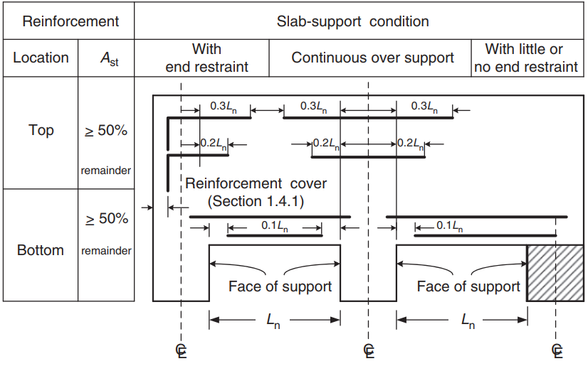
Figure 9. Reinforcement arrengement for one-way and two-way slabs. (Yew-Chaye Loo & Sanual Hug Chowdhury , “Reinforced and Prestressed Concrete”, 2nd edition, Cambridge University Press)
If you are new at SkyCiv, Sign up and test the software yourself!
SkyCiv S3D Plate Design Module Results
In the first view, we will show some images for the modeling and structural analysis of the example in S3D. We recommend you read about modeling in SkyCiv in the following links How to model plates? And ACI Slab Design Example with SkyCiv.
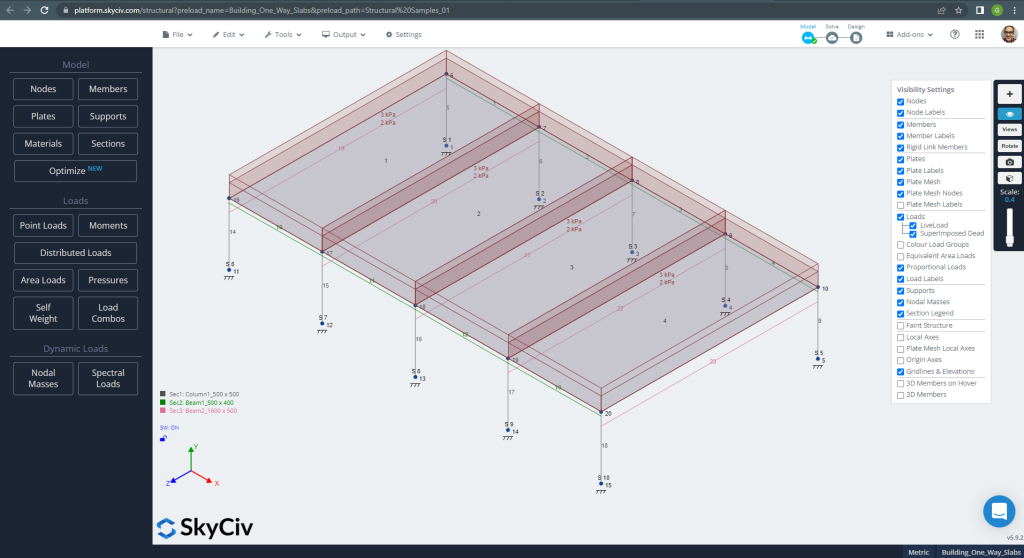
Figure 10. Structural Model in S3D for one-way slabs example. (Structural 3D, SkyCiv Cloud Engineering).
Before analyzing the model, we must define a plate mesh size. Some references (2) recommend a size for the shell element of 1/6 of the short span or 1/8 of the long span, the shorter of them. Following this value, we have \(\frac{L2}{6}=\frac{6m}{6} = 1m \) or \(\frac{L1}{8}=\frac{14m}{8}=1.75m \); we take 1m as a maximum recommended size and 0.50m applied mesh size.
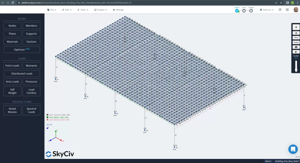
Figure 11. Improved mesh in plates. (Structural 3D, SkyCiv Cloud Engineering).
Once we improved our analytical structural model, we run a linear elastic analysis. When designing slabs, we have to check if the vertical displacement are less than the maximum allowed by code. Australian Standars stablished a maximum serviciability vertical displacement of \(\frac{L}{250}=\frac{6000mm}{250}=24.0 mm\).
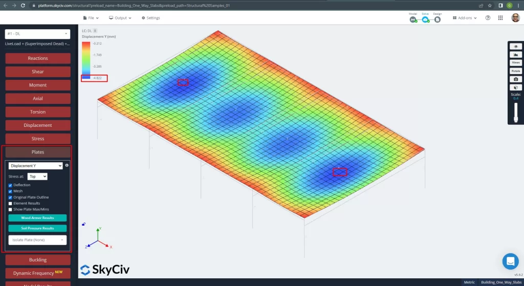
Figure 12. Vertical displacement in plates. (Structural 3D, SkyCiv Cloud Engineering).
Comparing the maximimum vertical displacement against the code referenced value, the slab’s stiffness is adequate. \(4.822 mm < 24.00mm\).
The maximum moments in the slab’s spans are located for positive in the center and for negative at the exterior and interior supports. Let’s see these moments values in the following images.
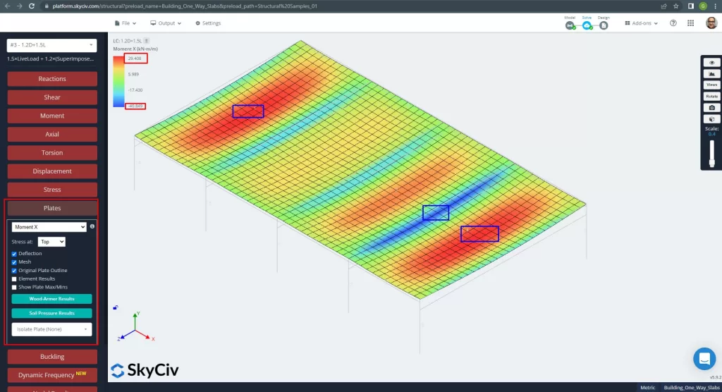
Figure 13. Moments in the X direction. (Structural 3D, SkyCiv Cloud Engineering).
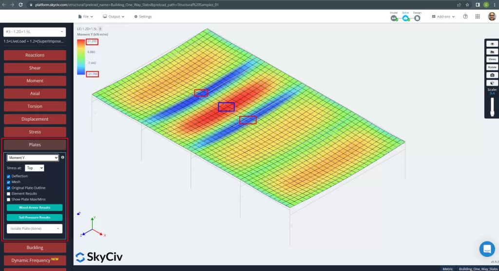
Figure 14. Moments in the Y direction. (Structural 3D, SkyCiv Cloud Engineering).
Plate element local axes are indicated below.
Figure 15. Slab local axes. (Structural 3D, SkyCiv Cloud Engineering).
For more details about automated reinforced slab design, see our documentation Plates in SkyCiv.
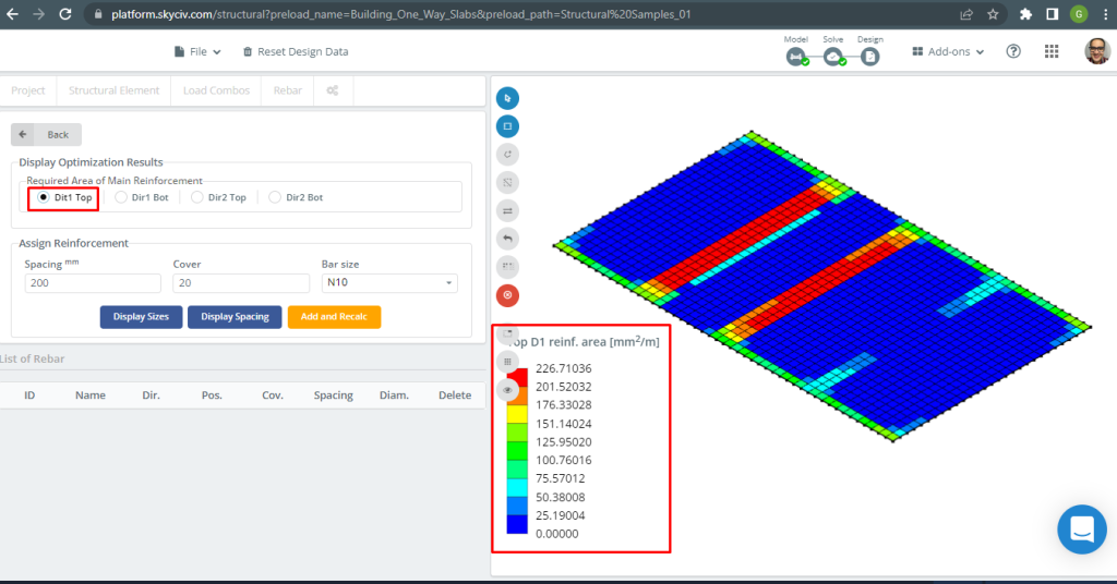
Figure 16. Top D1 reinforcement. (Structural 3D, SkyCiv Cloud Engineering).
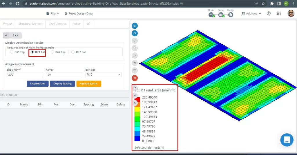
Figure 17. Bottom D1 reinforcement. (Structural 3D, SkyCiv Cloud Engineering).
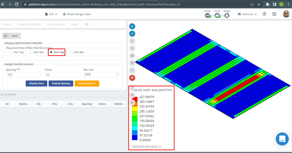
Figure 18. Top D2 reinforcement. (Structural 3D, SkyCiv Cloud Engineering).
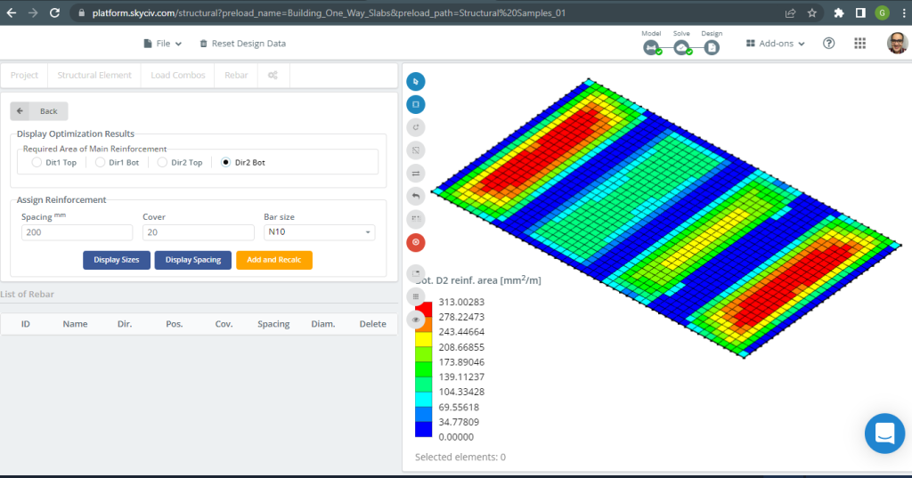
Figure 19. Bottom D2 reinforcement. (Structural 3D, SkyCiv Cloud Engineering).
Results comparison
The last step in this one-way slab design example is compare the steel rebar area obtained by S3D analysis (local axes “2”) and handcalculations.
| Moments and steel area | Exterior Negative Left | Exterior Positive | Exterior Negative Right | Interior Negative Left | Interior Positive | Interior Negative Right |
|---|---|---|---|---|---|---|
| \(A_{st, HandCalcs} {mm^2}\) | 334.82 | 436.31 | 481.099 | 481.099 | 334.8214 | 436.3100 |
| \(A_{st, S3D} {mm^2}\) | 285.13 | 313.00 | 427.69 | 427.69 | 313.00 | 427.69 |
| \(\Delta_{dif}\) (%) | 14.84 | 28.262 | 11.101 | 11.101 | 6.517 | 1.986 |
We can see that the results of the values are very close to each other. This means the calculations are correct!
Two-way Slab Design Example
In this section, we will develop an example that consists of a grillage system.
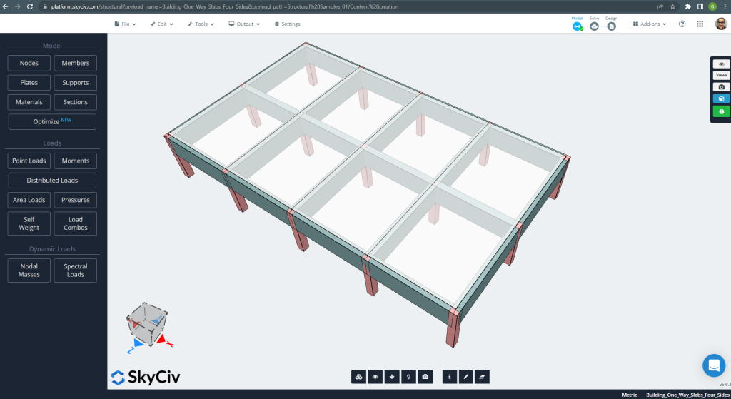
Figure 20. Grillage System. (Structural 3D, SkyCiv Cloud Engineering).
The plan dimensions are shown at next
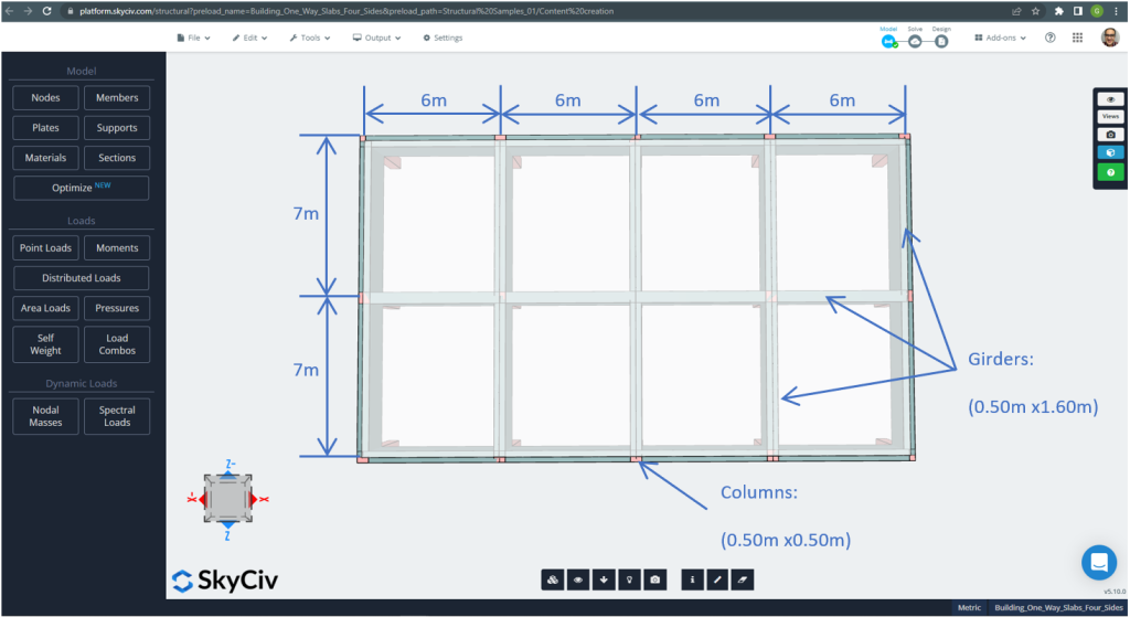
Figure 21. Plan dimensions for the four sides two-way slab example. (Structural 3D, SkyCiv Cloud Engineering).
For the slab example, in summary, the material, elements properties, and loads to consider :
- Slab type classification: Two – way behaviour \(\frac{L_2}{L_1} \le 2 ; \frac{7m}{6m}=1.167 < 2.00 \) Ok!
- Building occupation: Residential use
- Slab thickness \(t_{slab}=0.25m\)
- Reinforced concrete density assuming a steel reinforcement ratio of 0.5% \(\rho_w = 24 \frac{kN}{m^3} + 0.6 \frac{kN}{m^3} \times 0.5 = 24.3 \frac{kN}{m^3} \)
- Concrete characteristic compressive strength at 28 days \(f’c = 25 MPa \)
- Concrete Modulus of Elasticity by Australian Standard \(E_c = 26700 MPa \)
- Slab Self-Weight \(Dead = \rho_w \times t_{slab} = 24.3 \frac{kN}{m^3} \times 0.25m = 6.075 \frac {kN}{m^2}\)
- Super-imposed dead load \(SD = 3.0 \frac {kN}{m^2}\)
- Live load \(L = 2.0 \frac {kN}{m^2}\)
Hand calculation according to AS3600 Standard
In this section, we will calculate the required reinforced steel rebar using the reference of the Australian Standard. We first obtain the total factored bending moment to be carried out by the slab’s unitary width strips in each bending main direction.
- Dead load, \(g = (3.0 + 6.075) \frac{kN}{m^2} \times 1 m = 9.075 \frac{kN}{m}\)
- Live load, \(q = (2.0) \frac{kN}{m^2} \times 1 m = 2.0 \frac{kN}{m}\)
- Ultimate load, \(Fd = 1.2\times g + 1.5\times q = (1.2\times 9.075 + 1.5\times 2.0)\frac{kN}{m} =13.89 \frac{kN}{m} \)
Design moments and coefficients
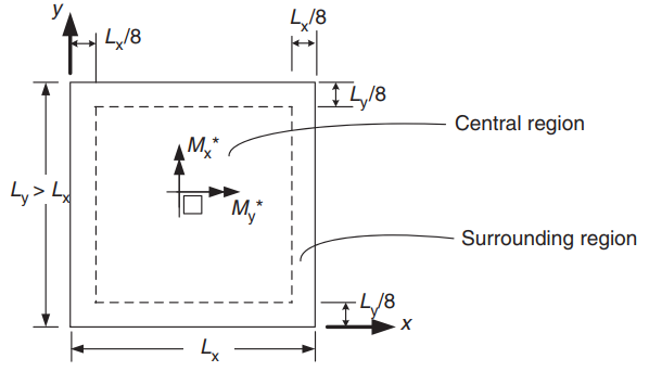
Figure 22. Orientation of a two-way slab for positive moments determination. (Yew-Chaye Loo & Sanual Hug Chowdhury , “Reinforced and Prestressed Concrete”, 2nd edition, Cambridge University Press)
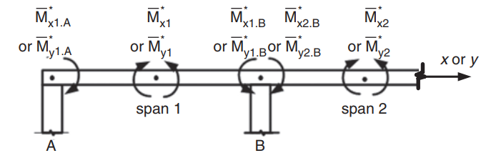
Figure 23. Negative moments determination in a two-way slab. (Yew-Chaye Loo & Sanual Hug Chowdhury , “Reinforced and Prestressed Concrete”, 2nd edition, Cambridge University Press)
| Edge Condition | Short-span coefficients (\(\beta_x\)) | Long-span coefficients (\(\beta_y)\) all values of \(\frac{L_y}{L_x}\) | |||||||
|---|---|---|---|---|---|---|---|---|---|
| Values of \(\frac{L_y}{L_x}\) | |||||||||
| 1.0 | 1.1 | 1.2 | 1.3 | 1.4 | 1.5 | 1.75 | \(\ge 2.0\) | ||
| 1. Four edges continuous | 0.024 | 0.028 | 0.032 | 0.035 | 0.037 | 0.040 | 0.044 | 0.048 | 0.024 |
| 2. One short edge discontinuos | 0.028 | 0.032 | 0.036 | 0.038 | 0.041 | 0.043 | 0.047 | 0.050 | 0.028 |
| 3. One long edge discontinous | 0.028 | 0.035 | 0.041 | 0.046 | 0.050 | 0.054 | 0.061 | 0.066 | 0.028 |
| 4. Two short edges discontinous | 0.034 | 0.038 | 0.040 | 0.043 | 0.045 | 0.047 | 0.050 | 0.053 | 0.034 |
| 5. Two long edges discontinous | 0.034 | 0.046 | 0.056 | 0.065 | 0.072 | 0.078 | 0.091 | 0.100 | 0.034 |
| 6. Two adjacent edges discontinous | 0.035 | 0.041 | 0.046 | 0.051 | 0.055 | 0.058 | 0.065 | 0.070 | 0.035 |
| 7. Three edges discontinuous (one long edge continuous) | 0.043 | 0.049 | 0.053 | 0.057 | 0.061 | 0.064 | 0.069 | 0.074 | 0.043 |
| 8. Three edges discontinuous (one short edge continous) | 0.043 | 0.054 | 0.064 | 0.072 | 0.078 | 0.084 | 0.096 | 0.105 | 0.043 |
| 9. Four edges discontinuos | 0.056 | 0.066 | 0.074 | 0.081 | 0.087 | 0.093 | 0.103 | 0.111 | 0.056 |
Table 1. (Yew-Chaye Loo & Sanual Hug Chowdhury , “Reinforced and Prestressed Concrete”, 2nd edition, Cambridge University Press)
The following image explain the all nine cases that the table above refers
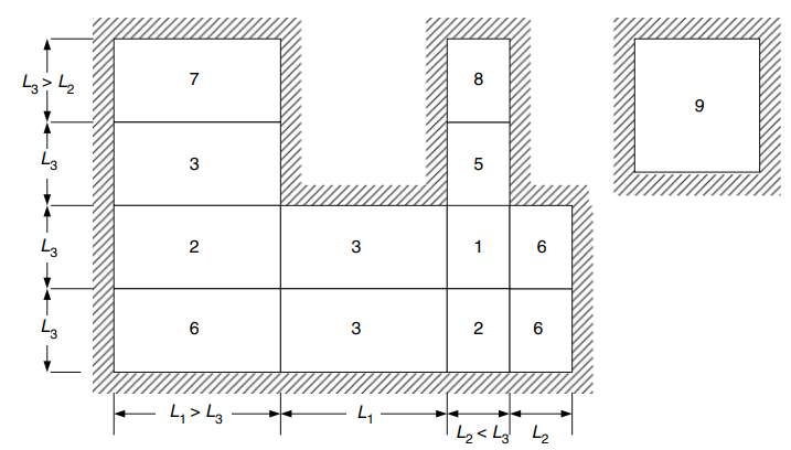
Figure 24. Edge conditions for two-way slabs supported on four sides. (Yew-Chaye Loo & Sanual Hug Chowdhury , “Reinforced and Prestressed Concrete”, 2nd edition, Cambridge University Press)
Design moments for central region (Case 6 Two adjacent edges discontinuous) :
- \(L_x = 6m, L_y=7m, \frac{L_y}{L_x} = \frac{7m}{6m}= 1.167 \) Values to be linearly interpolated
- Positives:
- \(M_x = {\beta_x}{F_d}{L_x^2} = {0.04435}\times {13.89 \frac{kN}{m}}\times{(6m)^2}=22.177 kNm\)
- \(M_y = {\beta_y}{F_d}{L_x^2} ={0.035}\times {13.89 \frac{kN}{m}}\times{(6m)^2}=17.501 kNm \)
- Negatives exterior span:
- \(M_{x1,A} = -\lambda_e \times M_x = -0.5 \times 22.177 kNm = – 11.089 kNm\)
- \(M_{y1,A} = -\lambda_e \times M_y = -0.5 \times 17.501 kNm = -8.751 kNm \)
- Negatives interior span:
- \(M_{x1,B} = -\lambda_{1x} \times M_x = -1.33 \times 22.177 kNm = – 29.495 kNm\)
- \(M_{y1, B} = -\lambda_{1y} \times M_y = -1.33 \times 17.501 kNm = -23.276 kNm \)
Design moments for central region (Case 3 One long edge discontinous) :
- \(L_x = 6m, L_y=7m, \frac{L_y}{L_x} = \frac{7m}{6m}= 1.167 \) Values to be linearly interpolated
- Positives:
- \(M_x = {\beta_x}{F_d}{L_x^2} = {0.03902}\times {13.89 \frac{kN}{m}}\times{(6m)^2}= 19.512 kNm\)
- \(M_y = {\beta_y}{F_d}{L_x^2} ={0.028}\times {13.89 \frac{kN}{m}}\times{(6m)^2}= 14.001 kNm \)
- Negatives interior span:
- \(M_{x1,B} = -\lambda_{1x} \times M_x = -1.33 \times 19.512 kNm = – 25.951 kNm\)
- \(M_{y1,B} = -\lambda_{1y} \times M_y = -1.33 \times 14.001 kNm = – 18.621 kNm \)
- Negatives interior second span:
- \(M_{x2,B} = -\lambda_{2x} \times M_x = -1.33 \times 19.512 kNm = – 25.951 kNm\)
- \(M_{y2,B} = -\lambda_{2y} \times M_y = -1.33 \times 14.001 kNm = – 18.621 kNm \)
Rebar steel for X direction
| \(\alpha\) and Moments | Exterior Negative Left | Exterior Positive | Exterior Negative Right | Interior Negative Left | Interior Positive | Interior Negative Right |
|---|---|---|---|---|---|---|
| M value | 11.089 | 22.177 | 29.495 | 25.951 | 19.512 | 25.951 |
| \(\rho_t\) | 0.00055614 | 0.00112 | 0.001496 | 0.001313 | 0.000984 | 0.001313 |
| ku | 0.015395 | 0.0310 | 0.0414 | 0.0364 | 0.0272 | 0.0364 |
| \(\phi\) | 0.8 | 0.8 | 0.8 | 0.8 | 0.8 | 0.8 |
| \(A_{st} {mm^2}\) | 334.8214 | 334.8214 | 335.08233 | 334.821 | 334.8214 | 334.8214 |
Rebar steel for Y direction
| \(\alpha\) and Moments | Exterior Negative Left | Exterior Positive | Exterior Negative Right | Interior Negative Left | Interior Positive | Interior Negative Right |
|---|---|---|---|---|---|---|
| M value | 8.751 | 17.501 | 23.276 | 18.621 | 14.001 | 18.621 |
| \(\rho_t\) | 0.0004383 | 0.0008811 | 0.001176 | 0.0009381 | 0.000703 | 0.0009381 |
| ku | 0.0121 | 0.0244 | 0.03256 | 0.02597 | 0.0195 | 0.02597 |
| \(\phi\) | 0.8 | 0.8 | 0.8 | 0.8 | 0.8 | 0.8 |
| \(A_{st} {mm^2}\) | 334.821 | 334.821 | 334.821 | 334.821 | 334.8214 | 334.821 |
If you are new at SkyCiv, Sign up and test the software yourself!
SkyCiv S3D Plate Design Module Results
After refining the model, is time to run a linear elastic analysis.
When designing slabs, we have to check if the vertical displacement are less than the maximum allowed by code. Australian Standars stablished a maximum serviciability vertical displacement of \(\frac{L}{250}=\frac{6000mm}{250}=24.0 mm\).
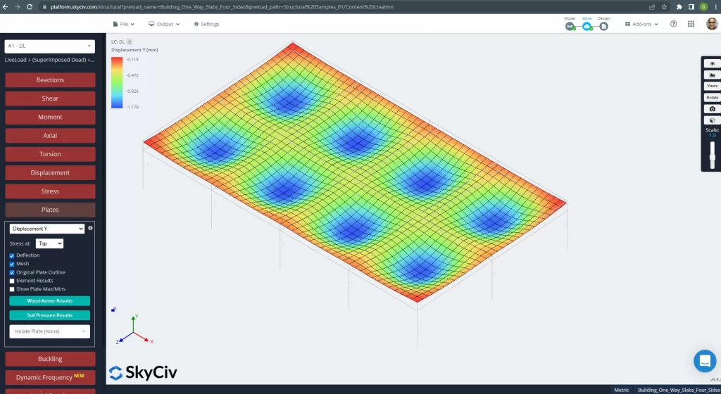
Figure 25. Vertical Displacement in the grillage slab system. (Structural 3D, SkyCiv Cloud Engineering).
The image above gaves to us the vertical displacement. The maximum value is -1.179mm being less than the maximum allowed of -24mm. Therefore, the slab’s stiffeness is adequate.
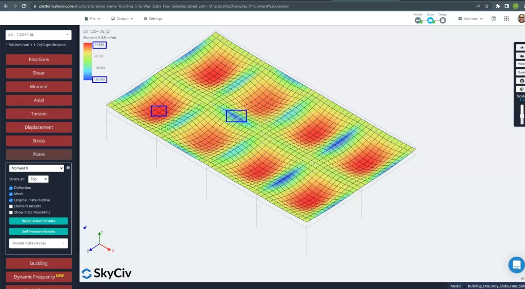
Figure 26. Plates moments in the X direction. (Structural 3D, SkyCiv Cloud Engineering).
Images 27 and 28 consist of the bending moment in each main direction. Taking the moment distribution and values, the software, SkyCiv, can obtain then the total steel reinforcement area.
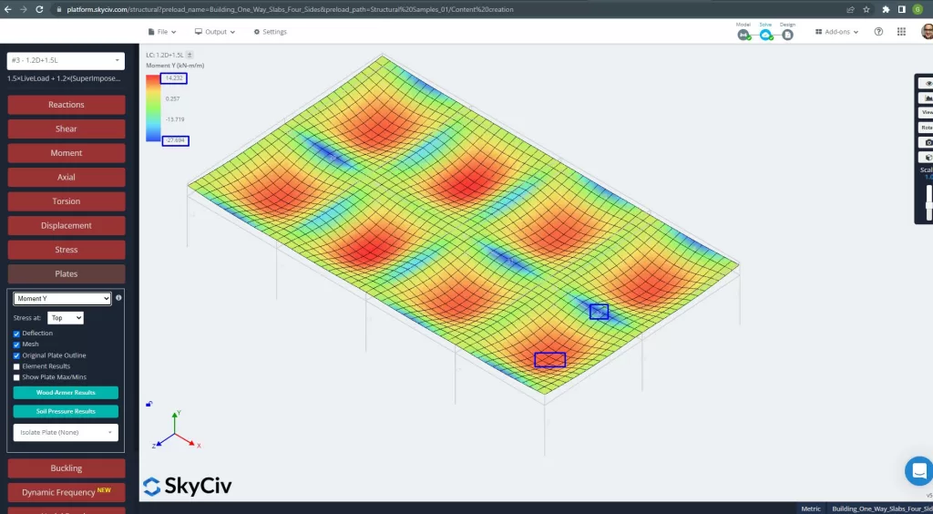
Figure 27. Plates moments in the Y direction. (Structural 3D, SkyCiv Cloud Engineering).
Steel reinforcement areas:
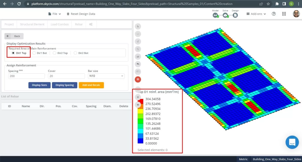
Figure 28. Top Steel Rebar Reinforcement in Direction 1. (Structural 3D, SkyCiv Cloud Engineering).
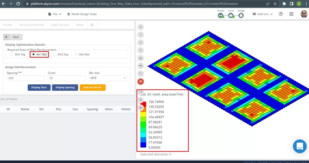
Figure 29. Bottom Steel Rebar Reinforcement in Direction 1. (Structural 3D, SkyCiv Cloud Engineering).
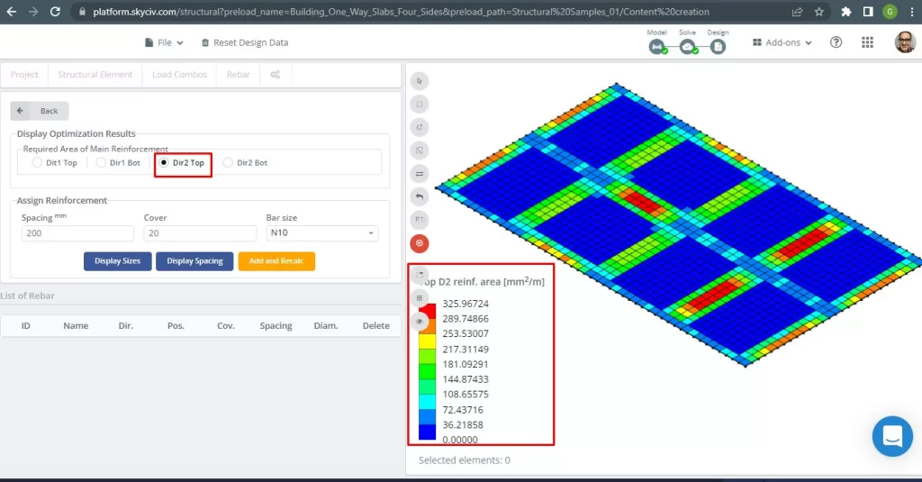
Figure 30. Top Steel Rebar Reinforcement in Direction 2. (Structural 3D, SkyCiv Cloud Engineering).
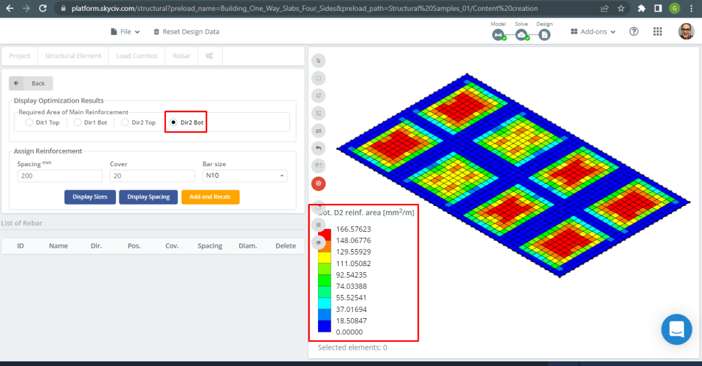
Figure 31. Bottom Steel Rebar Reinforcement in Direction 2. (Structural 3D, SkyCiv Cloud Engineering).
Results comparison
The last step in this one-way slab design example is compare the steel rebar area obtained by S3D analysis and handcalculations.
Rebar steel for X direction
| Moments and steel area | Exterior Negative Left | Exterior Positive | Exterior Negative Right | Interior Negative Left | Interior Positive | Interior Negative Right |
|---|---|---|---|---|---|---|
| \(A_{st, HandCalcs} {mm^2}\) | 334.8214 | 334.8214 | 335.08233 | 334.821 | 334.8214 | 334.8214 |
| \(A_{st, S3D} {mm^2}\) | 289.75 | 149.35 | 325.967 | 325.967 | 116.16 | 217.311 |
| \(\Delta_{dif}\) (%) | 13.461 | 55.39 | 2.720 | 2.644 | 65.307 | 35.0964 |
Rebar steel for Y direction
| Moments and steel area | Exterior Negative Left | Exterior Positive | Exterior Negative Right | Interior Negative Left | Interior Positive | Interior Negative Right |
|---|---|---|---|---|---|---|
| \(A_{st, HandCalcs} {mm^2}\) | 334.821 | 334.821 | 334.821 | 334.821 | 334.821 | 334.821 |
| \(A_{st, S3D} {mm^2}\) | 270.524 | 156.75 | 304.34 | 304.34 | 156.75 | 270.52 |
| \(\Delta_{dif}\) (%) | 19.203 | 53.184 | 9.104 | 9.104 | 53.184 | 19.204 |
The diference is some high for positive moments and the reason would be the presence of beams with high torsional stiffness that impact on the Plate Finite Element Analysis Results and the calculations for bending reinforcement steel.
If you are new at SkyCiv, Sign up and test the software yourself!
References
- Yew-Chaye Loo & Sanual Hug Chowdhury , “Reinforced and Prestressed Concrete”, 2nd edition, Cambridge University Press.
- Bazan Enrique & Meli Piralla, “Diseño Sísmico de Estructuras”, 1ed, LIMUSA.
- Australian Standard, Concrete Structures, AS 3600:2018