How to Import a DWG File into Structural Analysis Software
DWG is a very common binary drawing file format from Autodesk. It is a difficult file format for analysis software to process, given the data is very different. DWG files contain information of lines, points and text – whereas analysis software primarily need structural member, section and node information in order to perform a proper finite element analysis.
However, going from a 2D drawing (in DWG format) to an analysis model is a very common process for structural engineers, so SkyCiv has built some functionality to help engineers go from DWG to Analysis in a few simple steps. In this guide, we’ll walk you through how you can import DWG models into SkyCiv Structural 3D. Note: you will need access to SkyCiv Professional to use this feature.
Step 1: Import your DWG File
You can do this by clicking File – Import – DWG or by simply dragging and dropping your DWG file into the software:
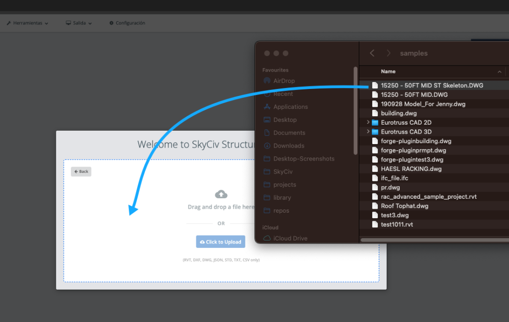
During this process, SkyCiv will upload your file and process it using Autodesks’s Forge API. This may take a minute while it reads and processes your file to prepare for step 2.
Step 2: Launch the SkyCiv Tracing Tool
Once your DWG shows, you’ll also see a bottom toolbar which shows the SkyCiv logo:
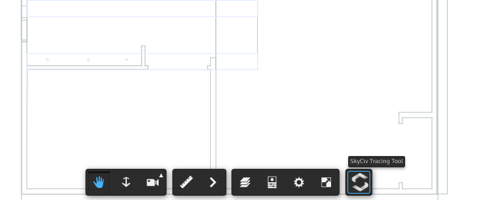
Once you click this, you’ll see a left panel appear and the cursor tool will change to a markup tool. You can now start marking up your model by snapping to the lines:
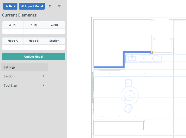
It’s helpful to know the following shortcuts:
- Double click to end the element
- Esc key will cancel the member
- Once a member is added, you can click to select and then hit Delete to remove
- If the drawing lines are too fine, you can change the Tool Size to help visualise your traced elements
- Change Section ID numbers to add other sections (which will appear in different colours)
- Scroll your mouse in or out to zoom in, making the tracing process easier
Step 3: Extract Data from Drawing to Table
Your current members and nodes will appear on the left tables under Current Elements. To pull the information from your right panel (the drawing GUI) into these tables, simply click the teal Update Tables button. This will also handle duplicate nodes within some tolerance to ensure you’re importing accurate information.
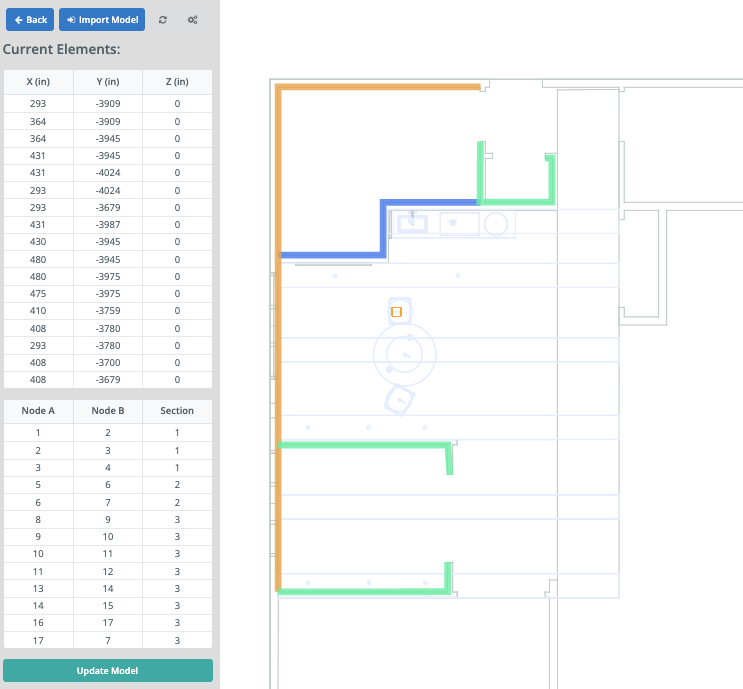
Once you’re happy with the data coming through on the tabes, click the blue Import Model to bring these elements into Structural 3D:
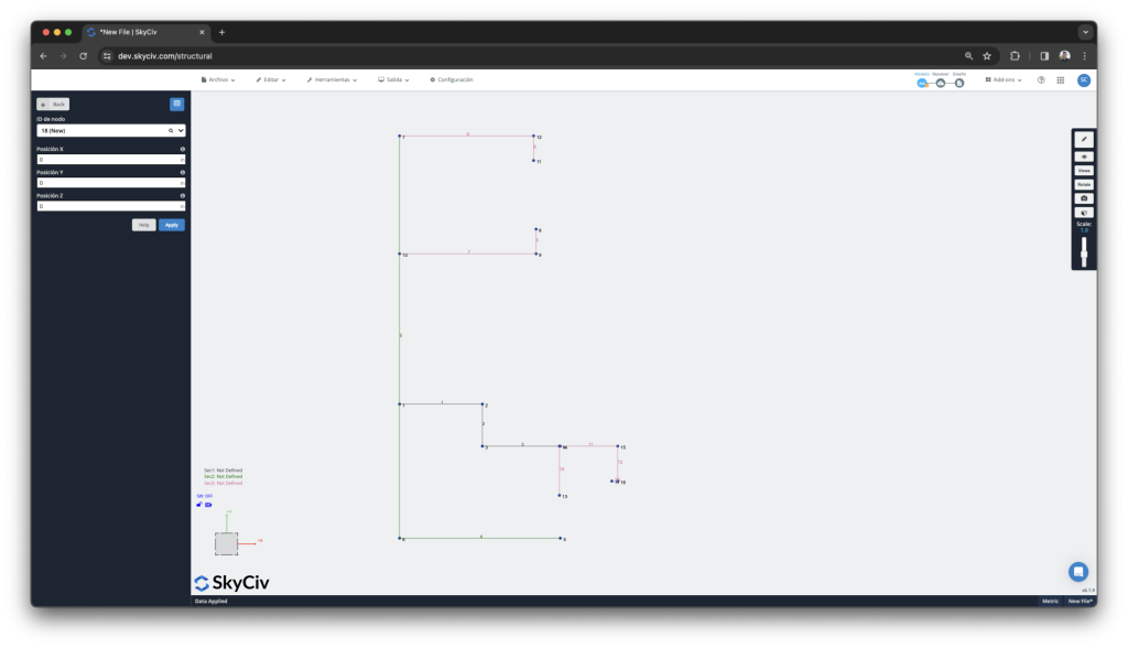
Your model is now imported with the defined section IDs. You can now start defining the cross section properties, applying loads and setting boundary conditions. We also recommend running a quick Repair Model to capture any accidental or incorrect elements (for instance two members not connecting, when they are really close).
You can also go back to the drawing by clicking File – Import – DWG again, your model and line elements will be right where you left them!
We hope this saves you time going from your DWG to Structural Analysis Models!