When modeling a structure in SkyCiv Structural 3D, members and connections are simplified with nodes and lines for members. These lines between nodes always run through the centroid of each member for simplicity and continuity. In reality, situations arise when the load acting on a member cannot be justified through its centroid, this is an eccentric load. Engineers need to think about eccentric loads when designing members because the addition of cross-sectional rotation, or Torsion, can, and most likely will, impact the limit state of the cross section.
For example: a point load on top of a cantilevered floor from above, or a hanging load off the side of a beam attached to stiffeners. A simple graphic of eccentric loads and how to interpret them is shown in Figure 1.
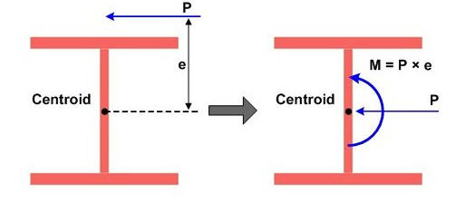
Figure 1: Example of eccentric load on an I-shaped cross-section
Source: http://manual.midasuser.com
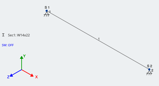
Lets take a look at an example in SkyCiv Structural 3D and apply an eccentric point load two different ways. First, lets assume we have a W14x22 beam that is 15 feet long with an eccentric point load at midspan of 10 kips, acting 12 inches away from the centroid. We will assume that the load is acting downward (-Y direction) and to the left side (+Z direction) of the member. Also, we will assume self-weight is off, for simplicity.
When modeling a single member, make sure that your supports are correct when modeling an eccentric load. The analysis wont run with both supports of your beam set as 3D pins because neither support will be resisting rotation of the cross section. In our case, the support further from the origin is only a 2D pin allowing rotation in the X and Y direction, coming from vertical and horizontal deflection. Lets take a look at our example member in the 3D modeling space:
Now, lets looks at the two methods of accounting for the eccentricity of our load. Referring to Figure 1, in our case:
\({P} = {10} kips\)
\({e} = 12 inches = 1 foot\)
Method 1: Accounting for eccentricity by applying a Moment
As shown in Figure 1, we can account for the eccentricity of the load by applying an additional moment at the centroid of the member. This moment is found by taking the point load multiplied by the moment arm, or “e”. We still need to account for the point load itself, so there will be (2) loads at the identified location.
In our case:
\({M} = {P}*{e}\)
\({M} = 10 kips * 1 foot = 10 kip-ft\)
As mentioned, this moment is now applied at the same location along the member as the eccentric point load. SkyCiv recognizes positive moment as counter-clockwise around the axis that is being applied, which is around the global X-axis in our case. See Figure 3 of these loads applied in SkyCiv 3D:
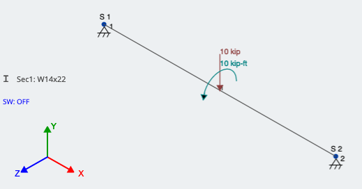
Figure 3: Modeling eccentric load by applying an additional moment
Method 2: Using rigid links
Another method is to use rigid links. Rigid Links are thought of as imaginary members that rotate and translate with whatever its connected to. They do not deflect between their nodes and are entirely stiff. Rigid Links are identified in the 3D modeling space as light grey and have a “R” next to them, as shown in Figure 4. Because they are used more for connecting elements and loads, they do need a size or section ID.
For our example, Node 6 is at midspan on the member. Node 5 is at the same X-coordinate, but 1.0 feet in the +Z direction; Node 5 is the actual location of the eccentric load.
Create/draw a member between the two nodes, and assign it as a Rigid Link. You can do this by pressing the Advanced switch in the member window, then going to Type and changing it to Rigid Link. Once applied, the member should look as described above. With one end signifying the actual location of the eccentric load and the other end connected to the member in the perpendicular direction, the load can finally be applied. This is shown in Figure 4; the red arrow is pointing to the Rigid Link:
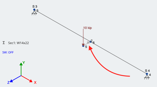
Figure 4: Using a rigid link to account for eccentricity of a point load
Final Comparison and Analysis:
Lets run a Linear Static Analysis and look at the results. We should be seeing the downward force of 10 kips in addition to a torsional component at the loading location. Both
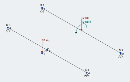
Figure 5: Both loading conditions for eccentric load
First, lets look at the reaction and moment results (Figure 6):
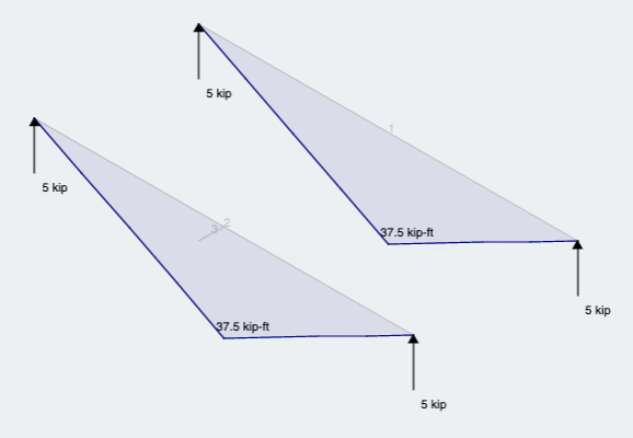
Figure 6: Reactions and Moment results for both methods
As expected we see what we would expect from the same magnitude load and location along the member, but through the centroid.
Subsequently, due to the eccentricity, we can observe that both members give the same result and show that the member is ALSO experiencing torsion (Figure 7):
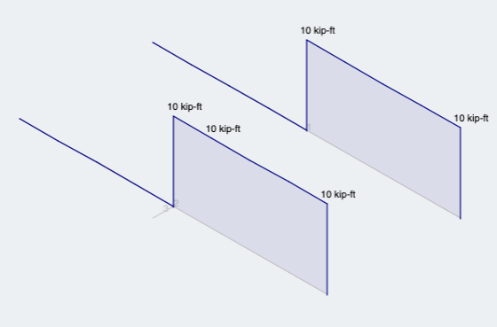
Figure 7: Torsion analysis results for both methods

Structural Engineer
BEng (Civil)