In this documentation, you will find tutorials on:
Plates
Plates are the two-dimensional elements of a structure most commonly used to model slabs, walls, and decks under applied loads.
Click here for more information on SkyCiv Plate Analysis Results
Creating Plates
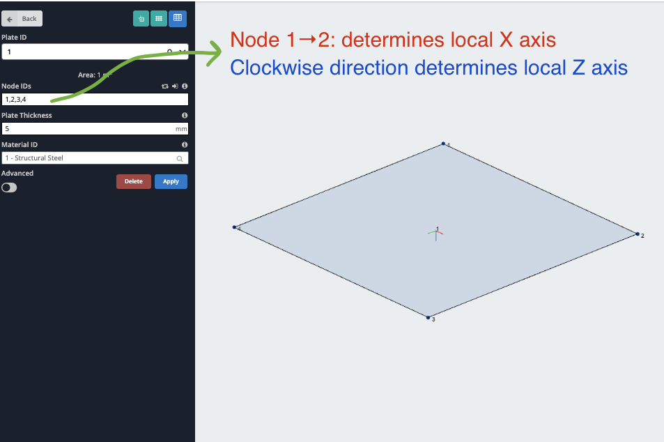
Plates can be created (and edited) via the form, the datasheet, or by using mouse controls. To use mouse controls, ensure you are in the plates menu. Click the nodes – without dragging – that form the plate. Click the last node a second time to end the plate.
To specify a plate in SkyCiv Structural 3D simply provide values for:
- Node IDs – The nodes which make up the plate. Specified by the node numbers separated by commas.
- Plate Thickness – The thickness of the plate. For thick Mindlin plates, it is recommended that the plate area to thickness ratio is below 8.
- Material ID – The ID used to identify the material of the plate.
Advanced Settings
The Advanced Settings for plates can be viewed by activating its toggle switch. Advanced form fields have blue labels, and include options for:
- Rotation Z – The rotation (in degrees) of the plate about its normal axis (its local Z-axis). This is important if you have multiple plates, aligning these connected plates ensures the results are interpreted correctly.
- Plate Type – The type of plate element. Mindlin plates are the recommended default. They take into account shear deformations which is appropriate for thick plates and is based on Mindlin-Reissner Theory. Kirchhoff plates do not consider shear deformations which are suitable for thin plates.
- Offset – Offset the plate perpendicular to its plane. Similar to member offsets, the plate is connected to the node locations using rigid links.
- Plane State – Choose whether to calculate Plane Stress or Plane Strain during the analysis of your plate
- Plate Thicknesses – individual force thicknesses can be defined for the following (Leave blank to use the main plate thickness value for that stiffness component):
- Membrane Thickness – Controls the thickness used for in-plane (membrane) stiffness, including axial and in-plane shear behavior
- Bending Thickness – Defines the thickness used for out-of-plane bending stiffness and flexural response.
- Shear Thickness – Sets the thickness used for transverse shear stiffness in plate or shell elements
- Drilling Stiffness Factor – controls the artificial rotational stiffness applied about a plate’s normal axis to improve numerical stability and prevent singularities during analysis.
As a plate is created, it will appear as a shaded region with a label. Plates are identified by their plate number which appears in the middle of the plate by default. Users can click and move the plate number label if they wish.
Troubleshooting Models with Multiple Plates
Sometimes larger structures (or structures with multiple plates) may fail to solve due to improper connectivity during the meshing phase. We highly recommend meshing all your plates at once to avoid issues like this.
If your structure has multiple plates and is failing to solve, we recommend re-meshing the structure all at once. The easiest way to do this is to:
- Select all (CTRL + A) and Click Advanced – Plates – Plate Mesher
- Click Unmesh to unmesh all your existing plates
- Select all the plates again (CTRL + A) and go back into the Mesher (Advanced – Plates – Plate Mesher)
- Then select Unstructured Quadrilaterals
- Click Mesh
The software will then mesh all your plates in one go – ensuring proper connectivity throughout your model. This is the most reliable method as it ensures adjacent plates are connected with common nodes.
Example
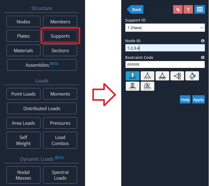
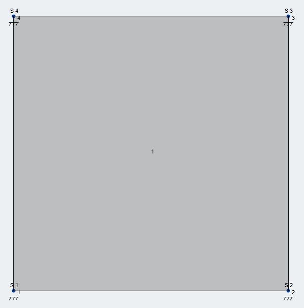
In this example, we will create a plate and apply some supports.
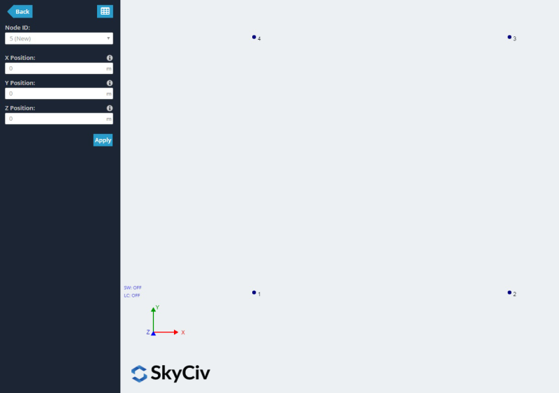
1) Plot the four nodes (0,0,0) , (1,0,0) , (1,1,0) and (0,1,0).
1. Using the Left Menu:
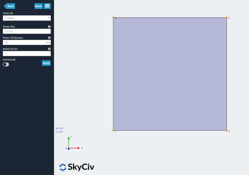
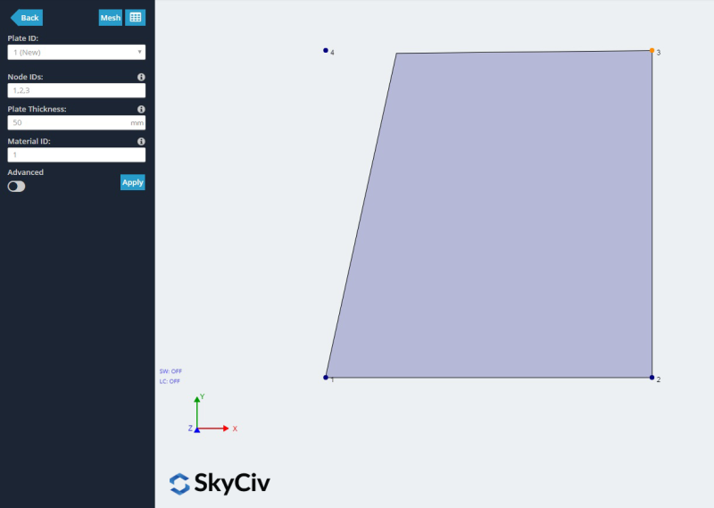
Firstly, plates can be created in a form by clicking the ‘Plates’ menu button on the left navigation bar. Specify 1,2,3,4 as the order of the plate nodes in the ‘Node IDs’ field. Click Apply.
2. Right Click:
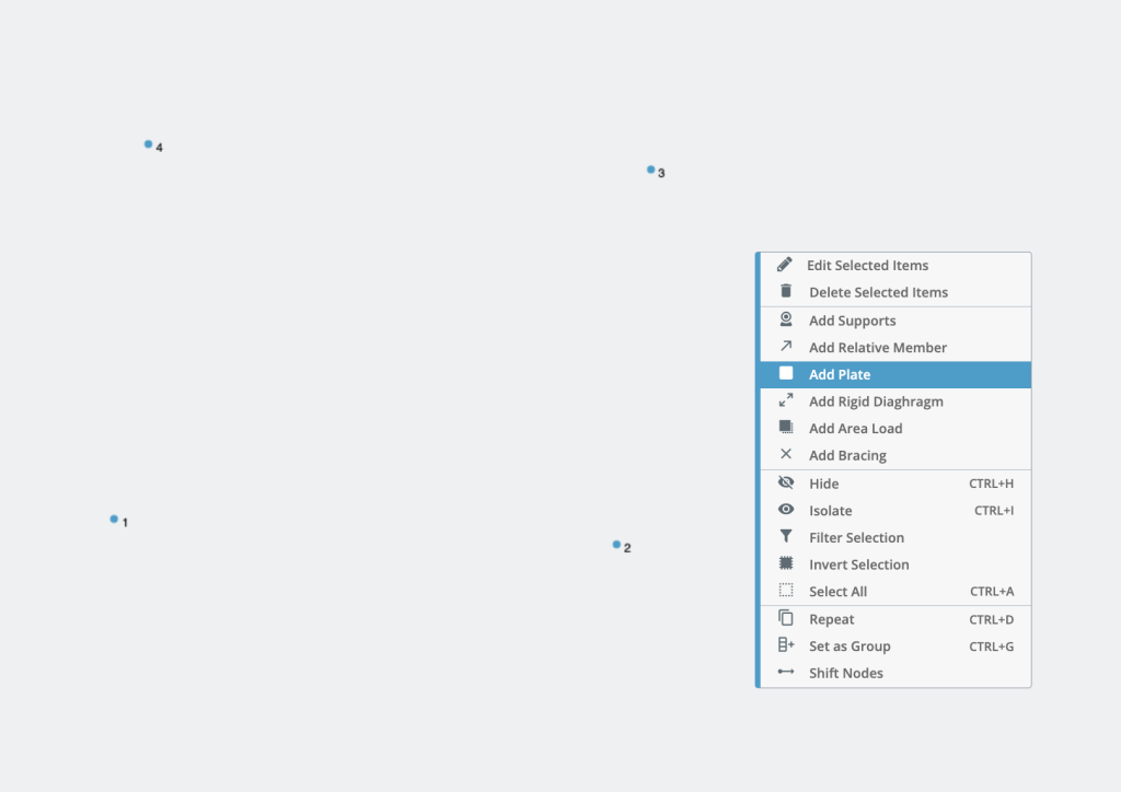
Highlight the nodes that will bound your plate, then right-click – Add Plate. The software will automatically put the nodes in a clockwise direction and apply a plate. Highlighting the nodes is easy with CTRL + Click drag (in two directions) or CTRL + A to select all nodes:
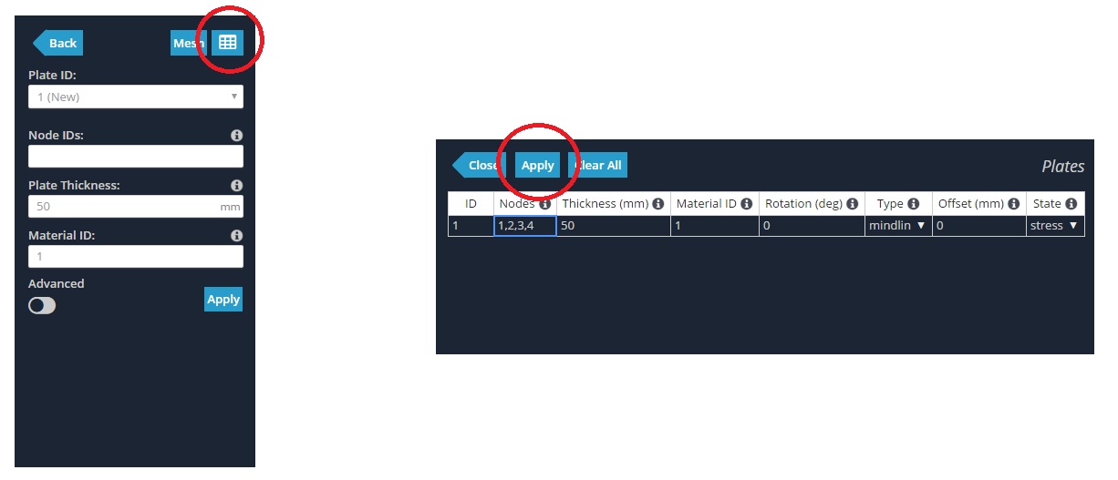
3. Using the Datasheet
Thirdly, plates can be created by clicking on the Plates Datasheet. This method is similar to the first, except in tabular format. It allows you to view or create many plates at once. Specify 1,2,3,4 in the ‘Nodes’ column and click apply to create a plate. Note, when specifying nodes in the table, order the nodes as they appear around the plate. i.e. go in a clockwise or counter-clockwise order to create a “string” of nodes that make up the plate.
4. Click Between Nodes:
Lastly, plates can be created by using mouse controls. To use mouse controls, ensure you are in the Plates menu. Click the nodes – without dragging – that form the plate. Click the last node a second time to end the plate.
Orthotropic Plates
Orthotropic plates can also be added in SkyCiv Structural 3D. In some situations, models may need to include plates with different mechanical properties in each orthogonal direction, meaning that the modulus of elasticity is not a single value anymore, but it has one value for each direction. Additionally, input for the shear modulus in each direction is also required.
To add orthotropic plates, first start by adding an orthotropic material (with Ex, Ey, Gxy, Gxz, Gyz, vxy) under the Materials menu in the advanced section, providing values for:
- Young’s Modulus x – Modulus of elasticity in the local x-axis (Ex)
- Young’s Modulus y – Modulus of elasticity in the local y-axis (Ey)
- Shear Modulus xy – In-plane shear modulus (Gxy)
- Shear Modulus xz – Shear modulus in the transversal plane is defined by the local axis xz (Gxz)
- Shear Modulus yz – Shear modulus in the transversal plane is defined by the local axis yz (Gyz)
- Poisson’s ratio xy – Poisson’s ration in plane xy (This value can be defined manually or let the input in blank in order to being auto-calculated based on the other material properties)
Please keep in mind that when the values for orthotropic material are provided, Young’s Modulus specified as a single value is ignored for the analysis of the plates with the orthotropic material assigned to them.
Note: If not sure about which is the physical direction of each plate’s local axes, go to visibility settings and toggle the “Local Axes” option (more information about visibility settings here)
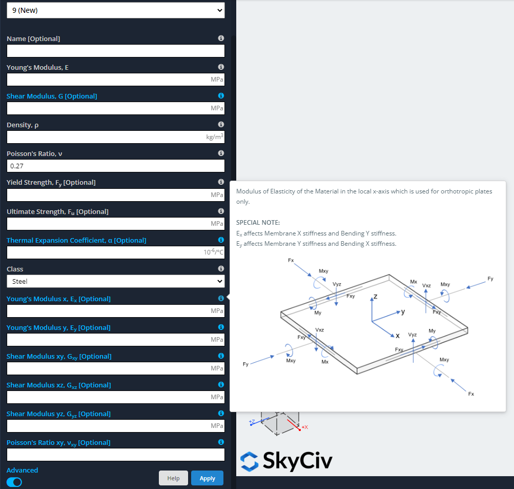
- Ex affects the membrane force Fx and the moment around axis “y” My (\(M_y = \int {-z}{\sigma_{xx}}{dz}\)).
- Ey affects the membrane force Fy and the moment around axis “x” Mx. (\(M_x = \int{-z}{\sigma_{yy}}{dz}\)).
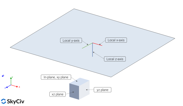
Plate – Node Connectivity
When modeling complex buildings, there will be a need to include Slabs elements and these can be modeled using Plate Elements according to the sections mentioned above. It is a must to correctly define node connectivity between elements such as beams and plates.
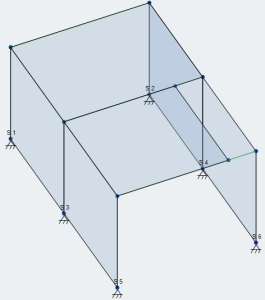
This section is going to show a short example that consists of a Reinforced Concrete one-level building.
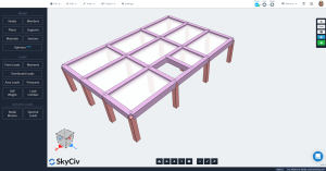
The elements modeled consist in:
- Moment frames to resist gravity and lateral loads.
- Columns dimensions: 500 mm x 500 mm.
- Beams dimensions: 500 mm x 700 mm.
- Concrete properties: f’c = 25 Mpa. (ACI-318)
The loads we will include in the model are:
- Gravity load: self-weight (SW).
- Lateral load (LL): a line load of 5 kN/m applied to beams in “z” direction.
- Load combination: SW + LL
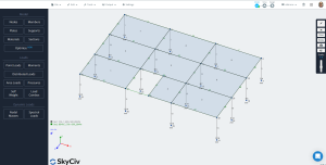
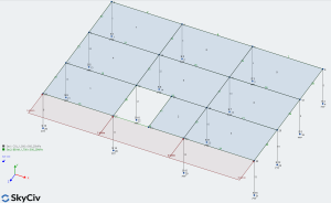
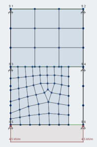
Before running the solver, which is a linear static analysis, we have to precisely mesh all the plates including elements in contact with them.
To do this meshing step, first, select all plates (ctrl+A), then go to ‘Edit’ and choose ‘Plate’ >> ‘Plate Mesher’ >> ‘Types of Elements: Unstructured Quadrilaterals’ and define a very fine granularity option using the slider or defining a small physical size to the mesh. We recommend the latest with 0.8m size.
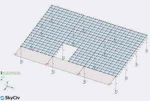
With a finer mesh, we can improve connectivity and avoid some issues in our structural models. See the next image
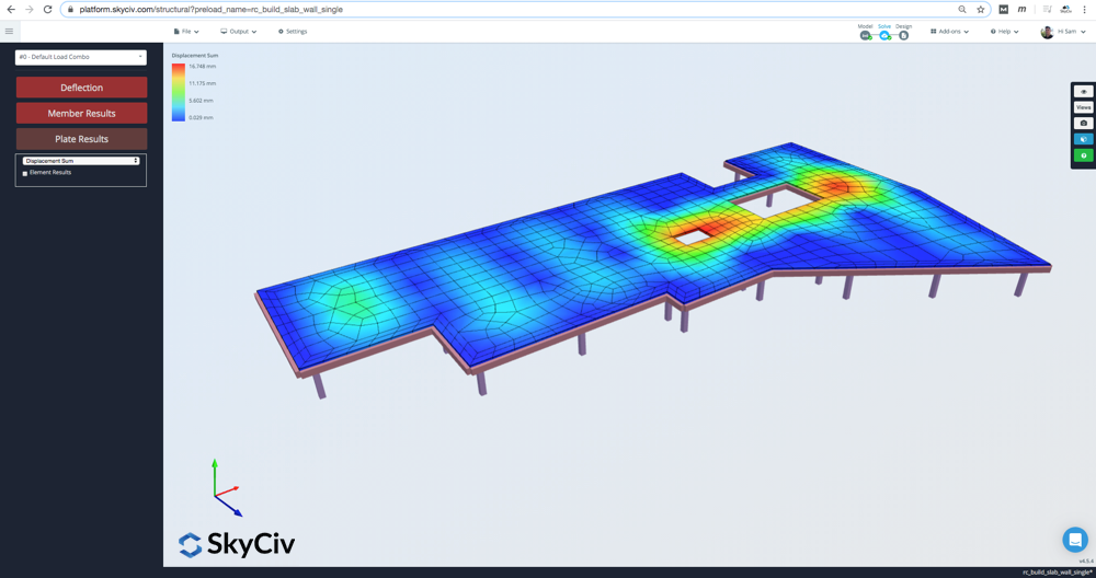
Finally, running analysis we can see that the lateral load has been transferred in an excellent way.
How to solve plate-node connectivity issues in your model?
If you have poor connectivity between members in your model, it will be necessary to improve them, in the majority of cases, changing some mesh properties. You will learn in the next example how to address the fix of a model.
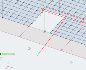
The following images are a sequence of steps to analyze a reinforced concrete tunnel.
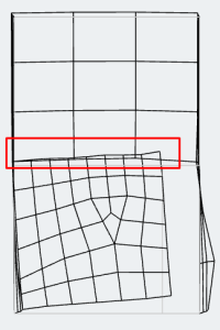
The first and second images are the structural model and a very poor mesh with a horizontal load, respectively. If we run the analysis without adjusting the model, we will obtain elements overlapping themself. This can be confirmed by looking at the red rectangle in the third image.
To fix this issue, it is needed to adjust the mesh for all plates. Go through the next step:
- Select all plates with “ctrl + A” and filter by plates (Filter options can be accessed by right click while elements are selected).
- Go to Edit >> Plates >> Plate Mesher >> select “Unmesh” to clean the plates from the irregular mesh (This option also can be used by right click and then ‘Unmesh’).
- Select again all plates and go to “Plate Mesher” as we did before to correctly mesh these elements.
- Change the type of elements in the Plate Mesher window to “Unstructured Quadrilaterals” and define a physical size of 0.4m (L/10).
- Apply the mesh. We will obtain a result as shown below.
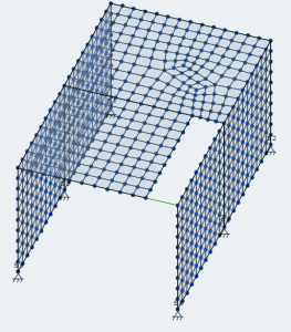
- Finally, run the analysis and observe how a correct mesh improves the result mainly by connecting well all nodes and elements.

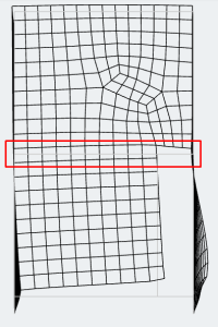
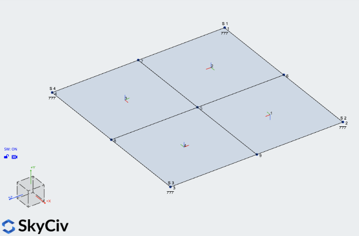
Plate Alignment
The Rotation setting in our plates will control any rotation in the plates local axis. By default, a simple plate will have it’s local axis determined by the first 3 nodes, like so:
The local axis of the plates (and corresponding meshed plates) becomes particularly important when you have multiple plates. In these cases, you can end up with connected plates that have different local axis references:
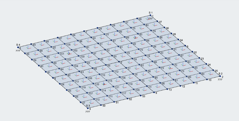
When reviewing results, this may cause problems as you’re not reviewing the different parts of the plates with respect to the same axis. To fix this, you can follow these steps:
- Right click one of the plates and click Plate Alignment Tool
- Align all the plates to a single reference plate – this will automatically align their local axis
- If you have already meshed your plate, select all your plates and click Re-align Meshed Plates – this will align the plates mesh to the parent plates local axis
You should now have all meshed plates aligning with the same axis, which will produce more consistant results across all 4 plates.
Free 14-Day Professional Trial
Make the most of SkyCiv Structural 3D by upgrading to our 14-Day Free Professional Trial.