Overturning Moment Calculation Example – Reinforced Concrete Cantilever
This is a simple guide on how to calculate overturning moment in a retaining wall with examples. The first stability check performed for a Cantilever Concrete Retaining Wall is against overturning. It refers to the capacity of the resisting forces to prevent the wall from rotating with respect to the most bottom left corner of the base for the action of the overturning forces. Those two load groups (resisting and overturning) are divided as follows:
Resisting loads:
- Retaining wall self-weight
- Active soil over the heel weight
- Surcharge load
Overturning loads:
- Active soil lateral pressure
- Lateral pressure that results from the presence of the surcharge
That said, the calculation process will be detailed in the following:
Input data:
Stem
- Height: 3.124 m
- Width: 0.305 m
- Offset: 0.686 m
Base
- Width: 2.210 m
- Thickness: 0.381 m
Active and Passive Soil
- Unit weight: 18.85 kN/m3
- Friction Angle: 35 degrees
Substructure Soil
- Unit weight: 18.85 kN/m3
- Friction Angle: 35 degrees
- Soil-Concrete Friction Coefficient: 0.55
- Allowable bearing pressure: 143.641 kPa
Soil Layers:
- Active: 3.505 m
- Passive: 0.975 m
- Substructure: 0.792 m
Surcharge Load Value: -17.237 kN/m
Vertical loads:
All the vertical loads to which the concrete cantilever retaining wall is subjected are shown in the following picture:
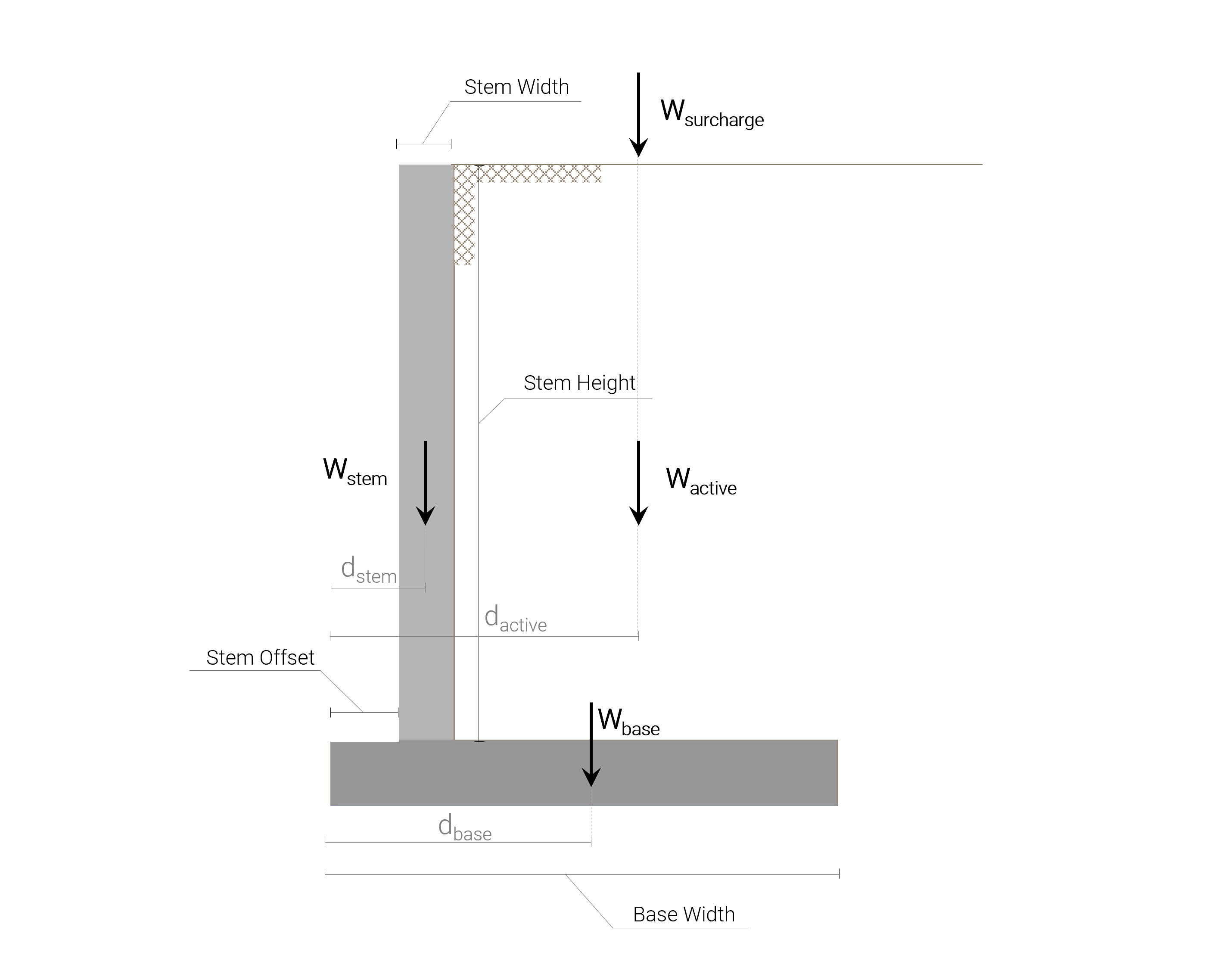
It is worth to mention here, that the weight (vertical load) and the moment associated with the portion of passive soil are neglected as it might be removed or eroded and it is a conservative assumption.
\(W_{stem} = \gamma_{concrete} \cdot (stem_{height} \cdot stem_{width} ) = 23.58 \;kN/m^3 \cdot 3.124\;m \cdot 0.305\;m\)
\( W_{stem}= 22.467\;kN/m\)
\(W_{base} = \gamma_{concrete} \cdot (base_{thickness} \cdot base_{width} ) = 23.58 \;kN/m^3 \cdot 0.381\;m \cdot 2.210\;m\)
\( W_{base}= 18.855\;kN/m\)
\(W_{active} = \gamma_{soil,\;active} \cdot (stem_{height}\cdot (base_{width}-stem_{offset}-stem_{width}) ) \)
\( W_{active} = 18.85 \;kN/m^3 \cdot 3.124\;m \cdot (2.210-0.686-0.305)\;m\)
\( W_{active} = 71.784\;kN/m\)
\(W_{surcharge} = surcharge_{value} \cdot ( (base_{width}-stem_{offset}-stem_{width} ) \)
\( W_{surcharge} = 17.237 \;kN/m \cdot (2.210-0.686-0.305)\;m\)
\( W_{surcharge} = 21.012\;kN/m\)
Restoring moment:
The restoring moment is the one in charge of preventing the wall from rotating with respect to the most bottom-left corner of the base. For calculating it, it is required to perform a moment summation with respect to the mentioned point of all the vertical loads:
\(M_{stem}=W_{stem}\cdot d_{stem} = 22.467\;kN/m \cdot 0.839\;m=18.839\;kNm/m\)
\(M_{base}=W_{base}\cdot d_{base} = 18.855\;kN/m \cdot 1.105\;m=21.939\;kNm/m\)
\(M_{active}=W_{active}\cdot d_{active} = 71.784\;kN/m \cdot 1.601\;m=114.89\;kNm/m\)
\(M_{surcharge}=W_{surcharge}\cdot d_{surcharge} = 21.012\;kN/m \cdot 1.601\;m=33.630\;kNm/m\)
\( \Sigma{M_{R}} = M_{stem}+M_{base}+M_{active}+M_{surcharge}\)
\( \Sigma{M_{R}} = 18.839+21.939+114.89+33.630\)
\( \Sigma{M_{R}} = 189.298\;kNm/m\)
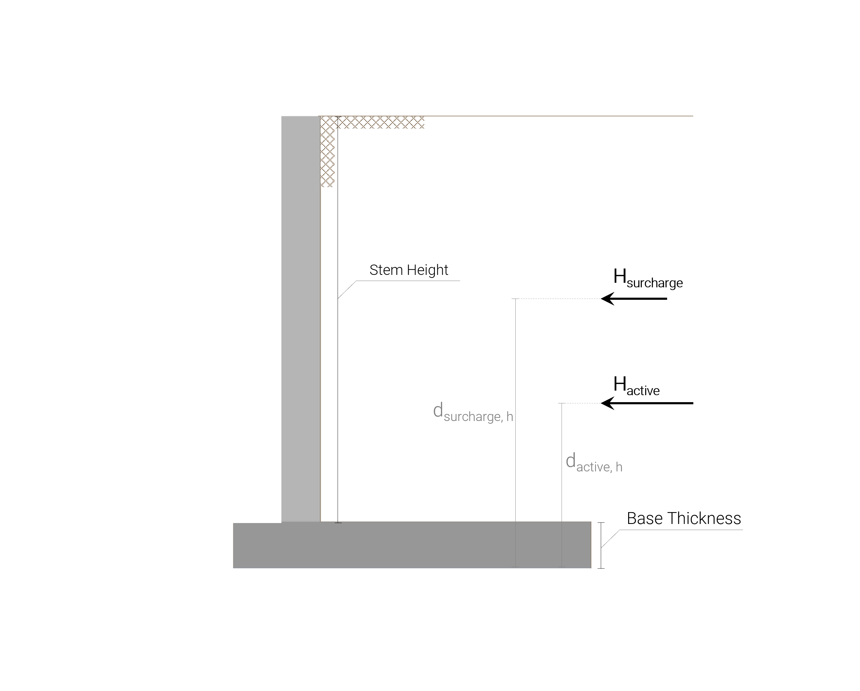
Horizontal loads:
All the horizontal loads to which the concrete cantilever retaining wall is subjected are shown in the following picture:
In order to calculate the lateral earth pressure due to the retained soil active pressure and the surcharge resultant lateral pressure, it is necessary to calculate the Rankine active earth-pressure coefficient:
\( K_a = \frac{1-\sin(\gamma_{soil,\;active})}{1+\sin(\gamma_{soil,\;active})} \)
\( K_a = \frac{1-\sin(35º)}{1+\sin(35º)} = 0.271 \)
With that result, it is now possible to calculate the horizontal load resulting from the lateral active pressure that the retained soil exerts:
\(H_{active} = \frac{1}{2} \cdot \gamma_{soil,\;active} \cdot (stem_{height} + base_{thickness})^{2} \cdot K_a \)
\(H_{active} = \frac{1}{2} \cdot 18.85\;kN/m^3 \cdot 3.505^{2} \cdot 0.271 \)
\(H_{active} = 31.377\;kN/m \)
For calculating the horizontal force related to the surcharge presence, an equivalent soil height is calculated first, and then the actual force:
\( h_{soil,\;eq} = \frac{surcharge_{value}}{\gamma_{soil,\;active}} = \frac{17.237 \;kN/m^{2}}{18.85 \;kN/m^{3}} \)
\( h_{soil,\;eq} = 0.914 \; m \)
\( H_{surcharge} = \gamma_{soil,\;active} \cdot h_{soil,\;eq} \cdot (stem_{height} + base_{thickness}) \cdot K_a\)
\(H_{surcharge} =\cdot 18.85\;kN/m^3 \cdot 0.914 \; m \cdot 3.505 \; m \cdot 0.271 \)
\(H_{surcharge} = 16.372\;kN/m \)
Overturning moment
The overturning moment is calculated as the moment generated by the horizontal loads with respect to the most bottom-left corner of the base. The lever arm distance for each of the horizontal loads will be:
- One-third of the wall’s height from the bottom of the base for the resultant of the active pressure distribution of the retained soil. It is like that since that pressure follows a triangular distribution with a zero value at the surface level and a maximum value at the bottom of the base level.
- One-half of the wall’s height from the bottom of the base for the case of the resultant horizontal load from the presence of the surcharge load. It is like that since that pressure follows a rectangular distribution.
That said, the overturning moment is calculated as follows:
\( M_{active} = H_{active} \cdot \frac{1}{3} \; (stem_{height} + base_{thickness}) \)
\( M_{active} = 31.377\;kN/m \cdot \frac{1}{3} \; 3.505\;m \)
\( M_{active} = 36.659 \;kNm/m \)
\( M_{surcharge, \;h} = H_{surcharge} \cdot \frac{1}{2} \; (stem_{height} + base_{thickness}) \)
\( M_{surcharge, \;h} = 16.372\;kN/m \cdot \frac{1}{2} \; 3.505\;m \)
\( M_{surcharge, \;h} = 28.692\;kNm/m \)
\( \Sigma{M_{OTM}} = M_{active}+M_{surcharge, \;h}\)
\( \Sigma{M_{OTM}} = 36.659 \;kNm/m+28.692\;kNm/m\)
\( \Sigma{M_{OTM}} = 65.351\;kNm/m\)
Factor of Safety against overturning
ACI 318 recommends a factor of safety to be greater than or equal to \(2.0\). It is calculated as follows:
\( FS = \frac{\Sigma{M_{R}}}{\Sigma{M_{OTM}}} \)
\( FS = \frac{189.298\;kN\ast m}{65.351\;kN\ast m}= 2.897 \ge 2.0\) PASS!
Retaining Wall Calculator
In this article, we have discussed overturning moment calculation examples. SkyCiv offers a free Retaining Wall Calculator that will check overturning moment and perform a stability analysis on your retaining walls. The paid version also displays the full calculations, so you can see step-by-step on how to calculate the stability of retaining wall against overturning, sliding and bearing!

Product Developer
BEng (Civil)