How to model stacked beams using Rigid Links
Simply specify the member “Type” as “Rigid Link” to create a member that acts as a Rigid Link. When this is done you will see that the rigid link is drawn with a light-grey color and has an “R” symbol beside it:

Rigid Links can be useful to define rigid connections between structures that involve stacked beams or members. They are often thought of as imaginary stiff links that join members so they can translate and/or rotate together. A rigid link can also be used to manually control for member offsets. Additionally, you can change the fixity/releases in the rigid link to control what forces and effects it has on what it connects to.
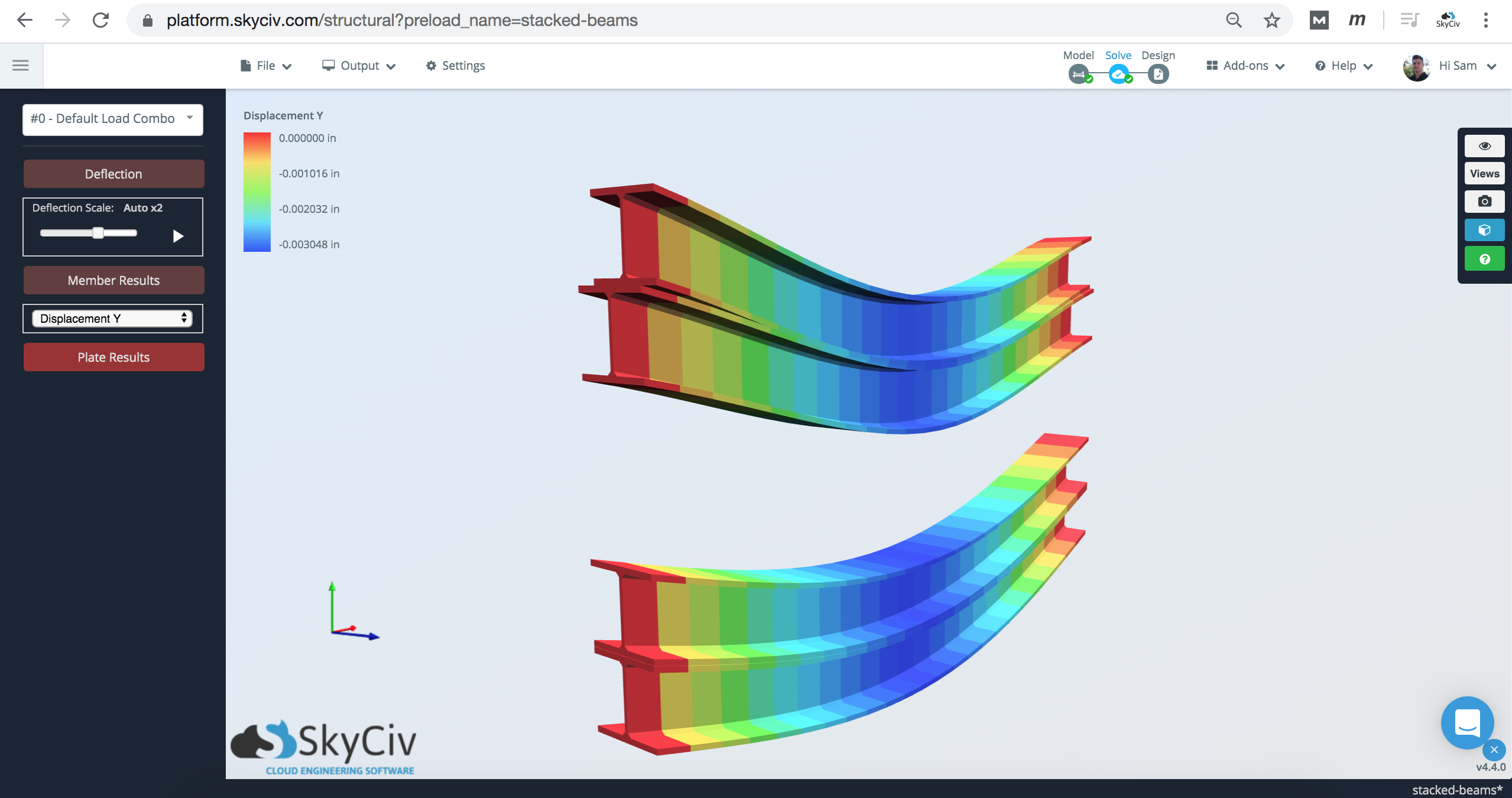
Looking at the analysis results, you can see that as the top beam is loaded, and deflects, so does the beam below:
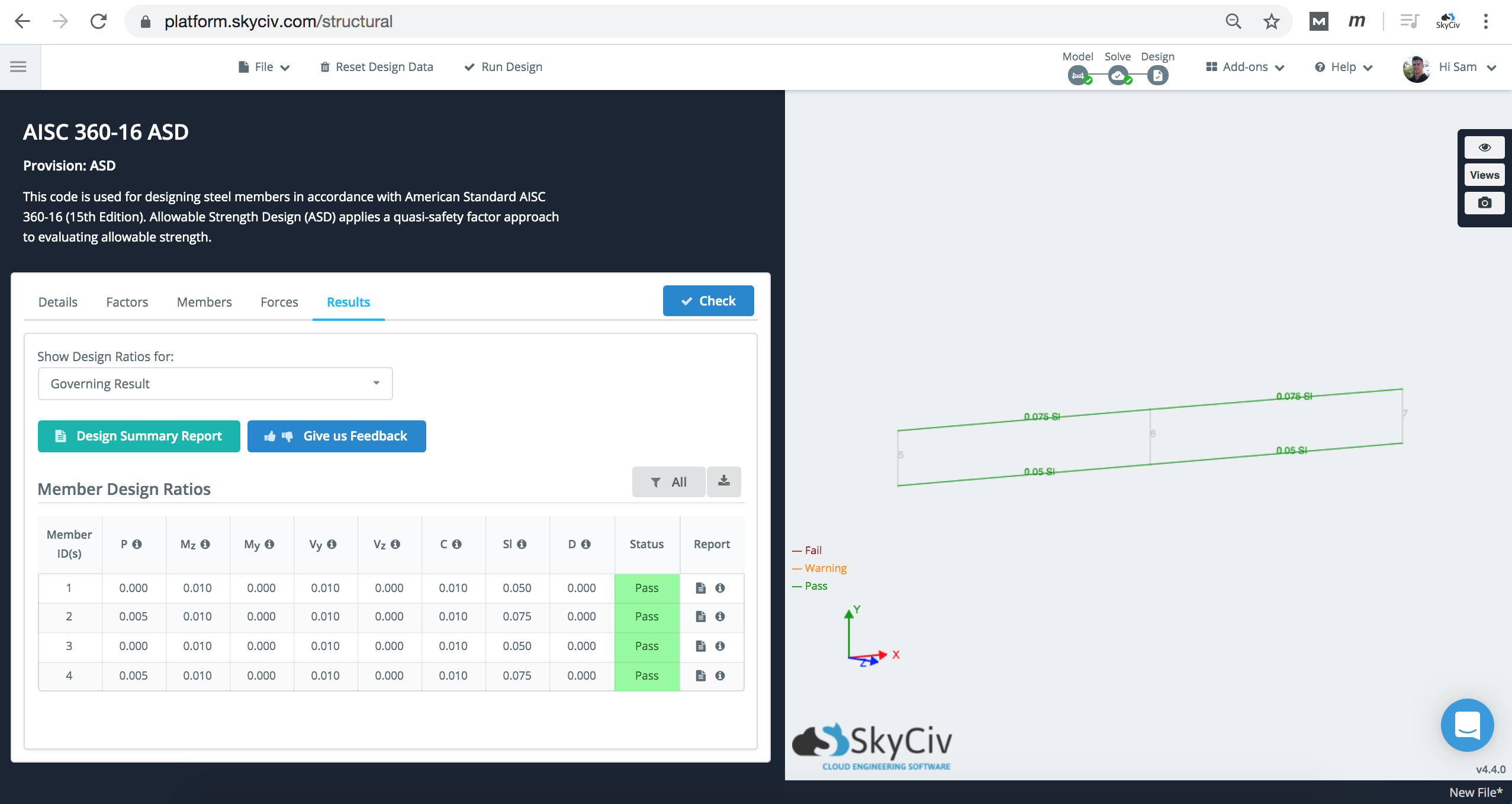
Member design checks will still run, however, it is important to consider the limitations of the software in understanding the unbraced lengths and member end fixities. In this scenario, the Lb should be adjusted according to your design needs.
Method 2: Using Custom Shapes in Section Builder
An alternative method to the above is using the SkyCiv Section Builder to model two models on top of each other, and treating it as one element:
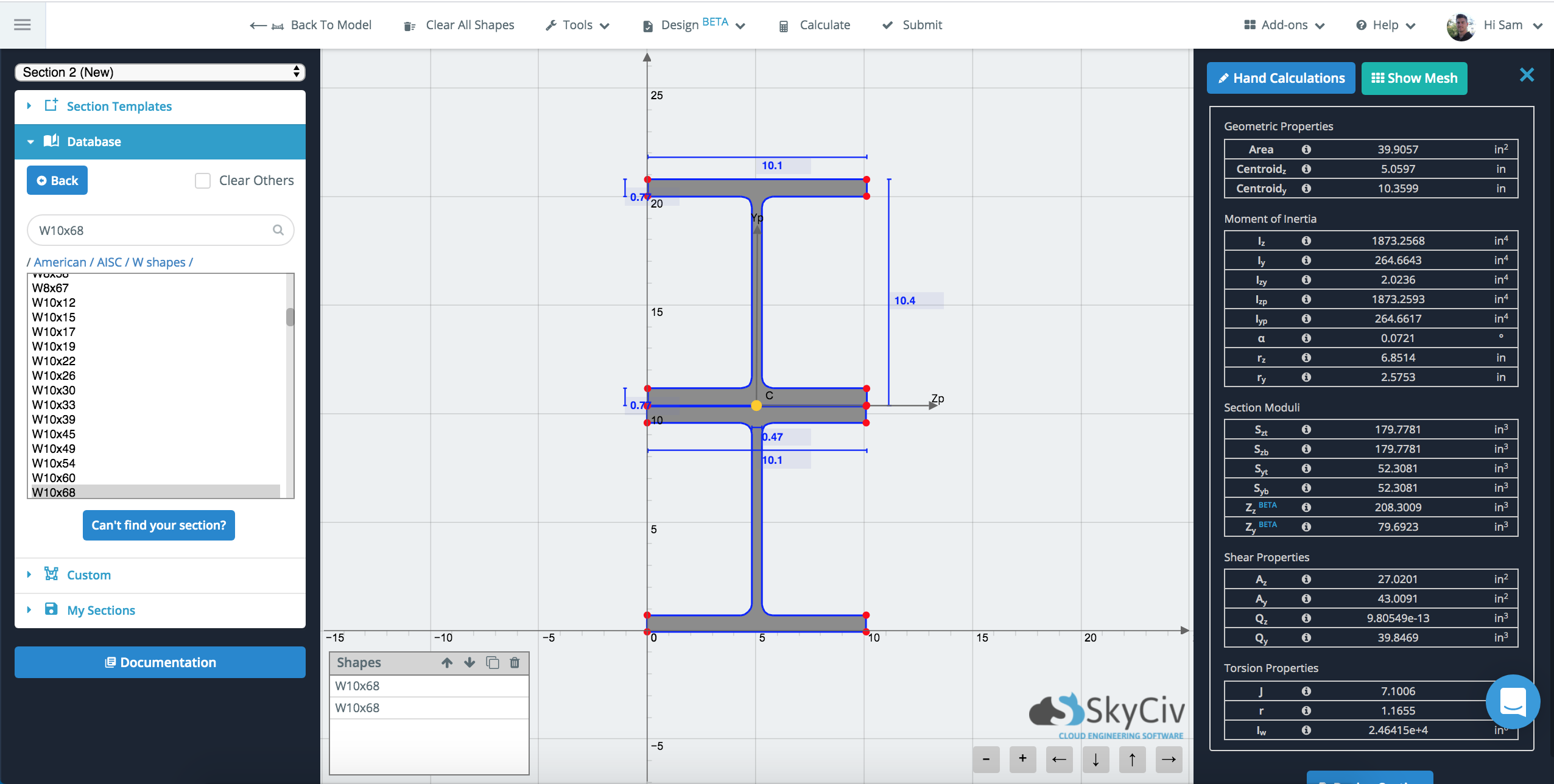
This will use FEA to calculate the geometric properties of this ‘single’ section. It will then use those geometric properties along with the entire line element. More on this method can be viewed on the following documentation page: Composite and Built-up Shapes in SkyCiv
Comparison of Results
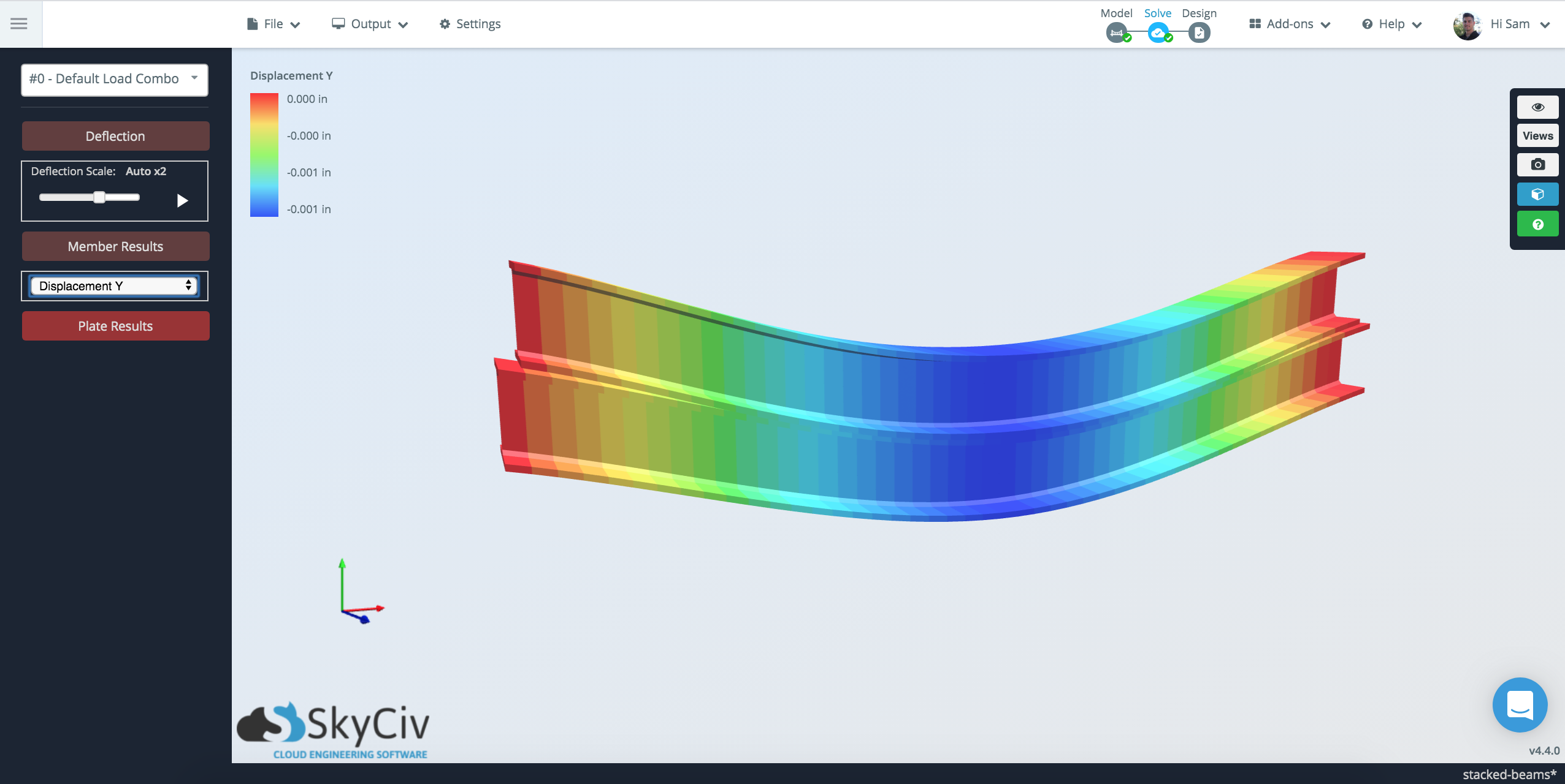
When modeling the two methods together, the results are quite consistent for deflection:
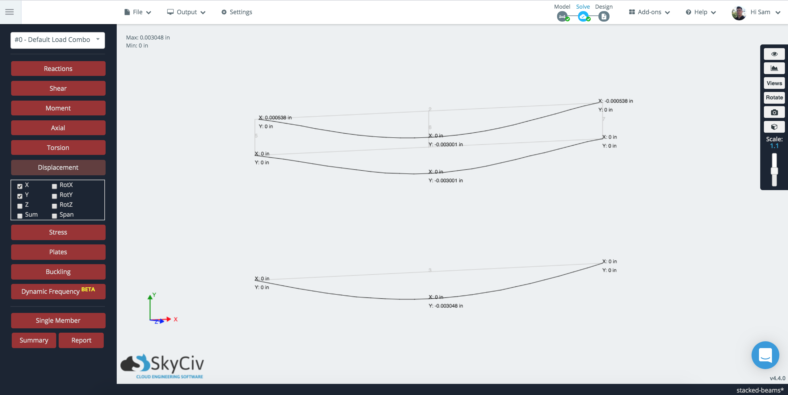
Since the members are only linked at certain points along the beam, there is a variance in the connectivity of the beams. In the bottom (Section Builder Method), the element is treated as one piece, whereas in the Rigid Link method, it is only connected at 3 points along the beam’s span.