A section is the cross-section geometry of the member. Different sections have different bending, shear, and torsional properties. Sections require a material assignment so that the geometry of the section can have material properties required for analytical and design calculations.
Sections can be created in two ways.
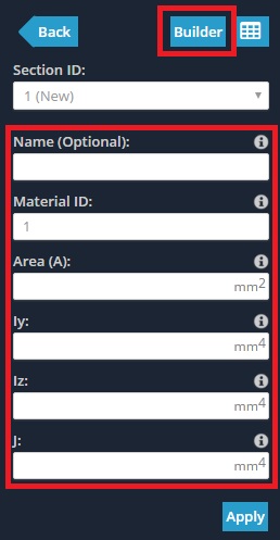
- In the form by directly specifying the values:
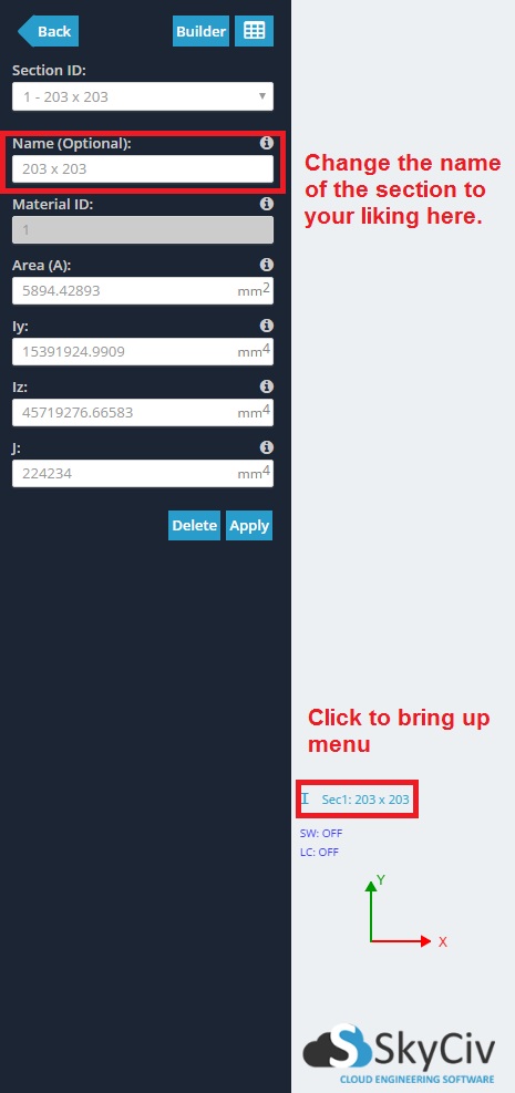
- Name (Optional)
- Material ID – The material of the section specified by ID.
- Area (without a direct shape assigned through the Section Builder, it will assume a rectangular cross-section)
- Iy – Moment of Inertia about the Y-axis
- Iz – Moment of Inertia about the Z-axis
- J – Torsion Constant
- Shear Area Y (Optional)
- Shear Area Z (Optional)
- Area Reduction Factor (Optional)
- Iy Reduction Factor (Optional)
- Iz Reduction Factor (Optional)
- Torsion Reduction Factor (Optional)
- Using the Section Builder
The datasheet can only be used to view sections. It cannot be used to add or edit sections.
Note: Shear Deformations (Euler-Bernoulli vs Timoshenko Beams)
If the shear areas are specified then shear deformation is taken into account (i.e. the member using the section is considered a Timoshenko Beam). In most applications, the shear deformation is negligible compared to flexural deformations.
When the shear areas are not specified in the section’s form then the shear area is taken as infinite, meaning that no shear deformations are accounted for (i.e. the member using the section is considered an Euler-Bernoulli Beam). It is recommended to keep the shear areas empty as shear deformation is usually negligible.
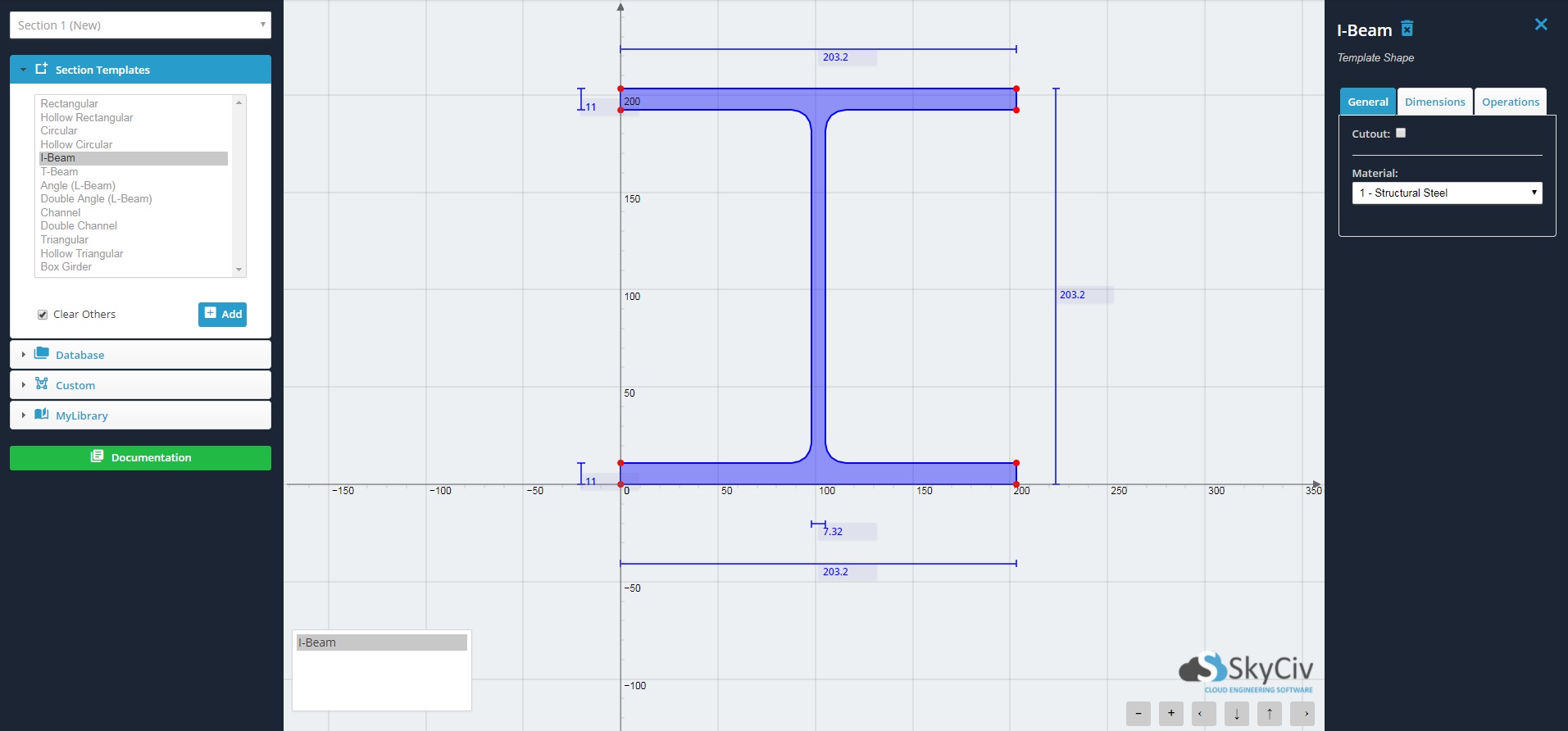
Section Builder
SkyCiv’s Section Builder is integrated into Structural 3D and allows users to quickly and easily model various types of sections.
- Rectangular
- Hollow Rectangular
- Circular
- Hollow Circular
- I-Beam
- T-Beam
- Angle (L-Beam)
- Double Angle
- Channel
- Double Channel
- Triangular
- Hollow Triangular
- Box Girder
For shapes not available in the templates, custom shapes can be defined in 3 different ways:
- Points Shapes – Define points to create a polygon. Specify fillets at any point.
- Line Shapes – Define a line path and create a polygon with a thickness and radius.
- Importing DXF – 2D shapes drawn in external CAD programs can be saved in DXF format and imported into SkyCiv’s Section Builder.
Built-up sections can be modeled by adding multiple shapes and performing operations (translating, rotating, mirroring) on them.
Composite sections can be modeled by assigning different materials to different shapes.
Note: SkyCiv does not currently support composite I-shaped beam design
Holes and cutouts can be specified by checking the “Cutout” box.
Clicking ‘Calculate’ will display a summary of the geometric, bending, shear, and torsional properties. However, it will NOT submit the section to the section ID.
Clicking ‘Submit’ will assign the section to the section ID. Members assigned with this section ID will have this cross-section.
Note: Cross-section assignment to member
It is important to note that when a member gets assigned to a cross-section, the line of the member always acts through the centroid of the section. This is to clarify that the (0,0) coordinate (origin) of the section builder is not by default the centroid. You can sketch and translate your section anywhere on the z-y cartesian plane, and the member will be assigned to the true centroid.
Translations and rotations of shapes allow for relative positioning of shapes when creating a section that is made up of more than 1 shape. If you don’t want the line of the member to pass through the centroid, then you can use the “Offset A” and Offset B” of the member.
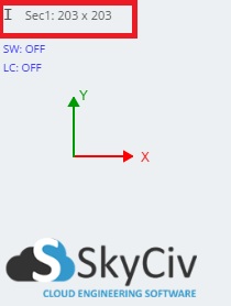
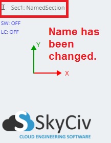
Example: How to name your sections
By default, when you add your sections, they will be named by their (rounded) height x width dimensions. To the left of the name will be an icon representing the section (e.g. in the example below the “I” icon represents an I-beam). If you are using a database section, the name will automatically default to the database section name and nomenclature but can be modified.